-
Thank you for visiting HeavyEquipmentForums.com! Our objective is to provide industry professionals a place to gather to exchange questions, answers and ideas. We welcome you to register using the "Register" icon at the top of the page. We'd appreciate any help you can offer in spreading the word of our new site. The more members that join, the bigger resource for all to enjoy. Thank you!
You are using an out of date browser. It may not display this or other websites correctly.
You should upgrade or use an alternative browser.
You should upgrade or use an alternative browser.
Boom lift Drive Wheels torque fade
- Thread starter Ronray
- Start date
You are right again TVA about the diagram with only one side going through the flow divider. Great memory you have! That would explain why 1 large Inlet port does not have high volume to the flow divider.
So now I am guessing that since the flow divider regulates the flow to one motor, that would increase or decrease flow to the other wheel motor, right? And it so happens that the flow divider regulates the pressure to the left side wheel, which was the one that would stop turning after a few inches of travel, while the other wheel was still spinning and digging further into the ground.
So maybe the spool in the flow divider was stuck in one position because of that tiny sleeve with the O-rings that was apparently accidentally reversed in one of the smaller spools could have been the cause?
At least I know now that I do not have a blocked internal passage and the valve manifold. So I guess my next step will be to reassemble everything and see how it works. Oh, and I have to check the hoses from the manifold to the motors to make sure there are no flaps or blockages.
Hello TVA. Just checking to see if you saw my last two posts.
As to how the hydraulic motors can reverse direction, I'm wondering if that would be controlled by the proportional valve that has the wires from the control lever and potentio meter. Which would mean that with two hoses coming from the proportional valve to the valve manifold we have been talking about, that each hose coming into the valve manifold would be for a different motor direction rotation forward or reverse, right? And since there are two large hoses going to each wheel motor, 1 hose would be for forward and the other hose would be for reverse?
As to how the hydraulic motors can reverse direction, I'm wondering if that would be controlled by the proportional valve that has the wires from the control lever and potentio meter. Which would mean that with two hoses coming from the proportional valve to the valve manifold we have been talking about, that each hose coming into the valve manifold would be for a different motor direction rotation forward or reverse, right? And since there are two large hoses going to each wheel motor, 1 hose would be for forward and the other hose would be for reverse?
Well, I reinstalled the valve manifold and now neither wheel gets enough torque to pull the machine forward or backwards. So now I am wondering if maybe the problem could be a lack of fluid pressure and volume from the proportional valve? And so I am thinking about switching the drive proportional valve with one of the other functions proportional valves as a test.
Also wondering if it would be preferable instead of pulling out the proportional valves, to just switch the Outlet hoses between the drive and lift outlet connectors of the manifold. See picture

Also wondering if it would be preferable instead of pulling out the proportional valves, to just switch the Outlet hoses between the drive and lift outlet connectors of the manifold. See picture
Well, I ended up switching the hoses from the drive and lift proportional valves as a test, and the Boom Lift operated at about two or 3 times faster, and the drive Wheels had even less torque. So I ruled out the Drive proportional valve as a potential cause.
So I read five or six Publications on troubleshooting hydraulics and I think I have a little better understanding of the difference between fluid pressure and fluid volume in producing wheel torque.
So I tested the inline pressure to the left wheel that would stop after moving several inches and with the swashplate opened up to maximum at 17 degrees to allow maximum flow, and got a pressure reading of 1200 lb, which I think would indicate that a pretty good volume of hydraulic fluid was still going through the hydraulic motor on the left side, but not enough volume of fluid to give the wheel enough torque to continue to dig into the ground.
Having set for a year now on the ground, all four wheels have sank about 6 or 8 in into the ground and apparently the wheels do not have enough torque to push the machine out of the rut. And since I live on a hillside with a 15-degree incline, I'm wondering if this machine will have enough to work to make it up the side of the Hill on a flat hard surface Road.
So I am wondering how to get more torque to these wheels, go with a higher GPM volume main pump, or possibly taking apart the Hub to see if there are planetary gears and possibly changing the gear ratios so that the wheels will turn more slowly, but with more torque? There is no diagram in the parts and service manual showing planetary gears in the hubs, even though it talks about planetary gears in the manual.
bus-junkie
Member
Hello Ronray, I have a friend's Marklift 62 that I'm helping him with and we are having the same wheel motor/drive problems (it seems). I sent one wheel motor away to be checked out and was told that there wasn't anything wrong that would keep it from working. They replaced a bearing and the seals (it took 5 months) and it is now back in. I've swapped several of the electric proportional valves operators to the drive valve and haven't had any better luck. This machine will have very slow operation of all it's functions until 5 or more minutes of running and then boom, extend, rotate etc. all work like they should. Once in a while it will drive better than others but I know it's not right. The longer it runs the worse the drive operation gets. I'll be watching your posts for insight for our rig.
Thanks Buss! Without me pulling apart the wheel hub, which looks large enough to have planetary gears inside, do you know if these wheels have planetary gears?
Also, do you know if having a higher GPM capacity main hydraulic pump would give the drive Wheels more torque?
Do you know what the normal pressure should be while the drive wheels are running on flat ground?
Also, do you know if having a higher GPM capacity main hydraulic pump would give the drive Wheels more torque?
Do you know what the normal pressure should be while the drive wheels are running on flat ground?
bus-junkie
Member
Yes, they both have planetary gears. I have not had them apart. I have had the brake off my right side while the wheel motor was out. To get the spline to line back up when putting the brake unit back into the planet hub I had to turn the cap around to depress the pin in the middle so I could rotate the splines without rolling the whole rig. They have gear oil in them and there is a way to add oil from the outside of the hub where that unlocking cap is located. The boomlift that we have turns both wheel motors the same so our problem isn't exactly like yours but does end up refusing to move like yours does. I am going to do the test like you did where you take the vent lines off the wheel motors and see how the compares from side to side. Our boom has two 'high speed' cylinders, one on each wheel motor like your (and my) diagrams show. I had the rod coming out of the cylinder on the right side come unthreaded from the spool inside the cylinder and it couldn't pull the swash-plate back all the way to 'low'. I tripped over this by accident while I had the wheel motor out having it rebuilt.
I'm not sure of the operating pressure yet as I'm still learning all these particulars like you are. I'm really thinking that I may have a problem in the pressure compensated flow divider. I will let you know as soon as I find out more. Please stay in touch. Thank you for posting your problem as I've been all over the internet and happened to find your posts here on this forum and I then joined.
I'm not sure of the operating pressure yet as I'm still learning all these particulars like you are. I'm really thinking that I may have a problem in the pressure compensated flow divider. I will let you know as soon as I find out more. Please stay in touch. Thank you for posting your problem as I've been all over the internet and happened to find your posts here on this forum and I then joined.
For some reason, my 2 speed shift lever cylinder keeps the wheel motor swashplate in the low speed 3 degree position, so I just disconnected the cylinder and manually tilted the swash plate levers to the full 17 degrees, which allows more oil to flow through the motors and thus more torque. In the Three Degree position, the wheels would not turn at all, but in the 17 degree full position, at least the wheels would turn several inches before failing to push the machine out of the ruts.
Also FYI, I completely disassembled and inspected and blew out the valve manifold block. Only one of the small spools had a small sleeve that was reversed. Prior to that, one wheel would spin while the other one locked up after rotating only a few inches. After disassembling and reassembling the valve block, now both Wheels turn for a few inches, but the one wheel does not continue to spin when the other one stops spinning.
My next step is going to be to jack up all four wheels to get them out of their ruts and see if that will propel the machine forward on level ground. I'm just not sure that this thing will have enough torque to propel the machine up a 15-degree incline.
To get more wheel torque, do you think that a higher GPM volume main pump would accomplish that? I also wonder if it would be possible to change the planetary wheel gear ratios?
bus-junkie
Member
Looking at the hydraulic schematic of the proportional valve bank, it looks like each spool has it's own pressure regulator. I'm going to check this out soon as I can.
Actually I think I was wrong on the location of the pressure relief valve. It looks like it is teed into the extension function circuit on the proportional valve manifold. And the exit hose oddly goes to the emergency Electric pump and then back to the holding tank.

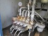
Bus, below is a schematic of my proportional valve Bank. Which symbol on the schematic would indicate a pressure regulator? Also below is a picture of my valve Bank proportional valves. If each one has a pressure regulator, would it be adjustable, and would that be the Allen screw on the end of each valve or whatever that thing is above each valve?


bus-junkie
Member
can you get me a picture of what you thought was your pressure regulator but taken from a little further away showing more hose and surrounding features?
Bus, you can zoom in on the Allen screws in the picture just below the names of the functions that are hand painted in yellow. You said you switched out the proportional valve between the drive function and other functions. Did that include switching out those parts with the Allen screws?
bus-junkie
Member
I meant that I did swap out the coils which are held in by the allens. They use voltage to send pilot oil to the covers just above the coils (held by allens also) and their corresponding covers on the back of the valve bank. The pilot oil pressure pushes the main spool back and forth.
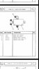
I took an inline pressure reading of 1200 PSI on one of the wheel Motors where the wheel would stop turning after moving a couple of inches. And my guess is that the pressure relief valve activated and diverted the flow since the pressure relief valve is set at 1200 PSI according to the manual. So I am wondering if I would be okay too adjust the pressure up to 2400 lb on the pressure relief valve and see if that would give more torque and volume to the hydraulic wheel drive motor? And if that is okay, then my next question is where do I make the adjustment on the pressure relief valve? Attached is a diagram and picture of the pressure relief valve showing a large nut on the right side. And I am wondering if that large nut is what makes the adjustment?


Attachments
bus-junkie
Member
I have a pressure gauge on main line pressure on the valve bank. I also have a gauge on the line where the hose to one of the wheel motors comes out of the flow divider in back. I can get 2400 lbs showing on the main gauge and only like 1400 on the gauge at the wheel motor hose. Not sure what to do next. I don't have a block like the one in your picture.