bus-junkie
Member
Where is this block located on your machine?


DCV is Directional Control Valve. The one you have the picture of.TVA, what is DCV?
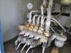
If you look closely at my picture of the pressure relief valve block, you will see that it is bolted alongside a larger valve block with the same bolts. I think it is strange that both hoses from the boom extension proportional valve also go into this pressure relief valve (see picture) which seems to be the only pressure relief valve for the entire system. I only confirmed that this was the pressure relief valve by looking at the hydraulic schematic and hydraulic hose kit pages in my PDF service and parts manual below and also the parts list diagram in my above post.
I also think it's odd that in the hose diagram below and on my machine, it appears that the pressure relief valve exit hose going back to the holding tank goes through the emergency pump?
Like yourself bus, I had 2700 lb of pressure on the portional valve bank, but 1200 lb on the wheel motor gauge.
View attachment 195630 View attachment 195631
The main relief ( extreme left, on the bottom) is a safety RELIEF ( meaning it’s opens at set pressure and drains to tank) is a safety feature and regulates pressure in “pressure gallery” of DVC, but each section can have its own PRESSURE REDUCING valve ( closes passage at set pressure), it’s own flow reducer, port reliefs, load check, regeneration, and etc. valves. I need to see your diagram to know what’s in it. Yours probably using fixed displacement pump and it does have relief valve ( I can see it on the picture).I have a pressure gauge on main line pressure on the valve bank. I also have a gauge on the line where the hose to one of the wheel motors comes out of the flow divider in back. I can get 2400 lbs showing on the main gauge and only like 1400 on the gauge at the wheel motor hose. Not sure what to do next. I don't have a block like the one in your picture.
TVA, I think I may be confusing the DVC with the flow diverter valve in the wheel motor valve manifold. Would you be able to Circle the part you are talking about in red and post it here? You're not talking about the valve block that the pressure relief valve block is bolted together with the same bolts, are you?[/QUOT
I’m sorry! DCV - the main control valve, but it does have pressure reducing valve at in each section, and yes your boom extension section has one external port pressure relief valve and looks like holding valve block on cylinder it’s self, also your lift circuit have emergency needle valve with fixed orifice, to slowly let boom down when both main engine and emergency motor is not operational.
Yes it will, but you can have normal pressure in Main Control Valve gallery, but your drive section can have lower pressure if the pressure reducing valve in that section is bad or miss adjusted!Thanks TVA. In my case wouldn't the gauge that I've got installed on the main pressure line coming into my valve bank also show low pressure if one of the motors or both are loosing/leaking oil?

Looks like the one on top is a external port relief for boom extension cylinder.Pressure relief valve block location
View attachment 195634 View attachment 195635 View attachment 195636

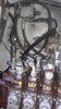
Not 100% sure, but I think that’s where the pilot control hose supposed to connect to!TVA, okay would the pressure reducing valve be the one in this picture with the Allen wrench inserted in this picture on the lift function? I noticed that the Allen screws on all of the functions are in different positions. So I assume this would be because they all have different reduced pressure settings?
View attachment 195641
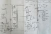
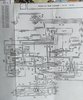
The designations on hose diagram is hard to read on my end, if pressure relief has one port connected to extension cylinder and other to tank then it is extension cylinder port relief valve.TVA, my pump is a variable displacement pump 2-32 cid. Does the 2 signify two pistons? If a variable displacement pump does not have a main pressure relief valve , then the pressure gauge for the main galley should read 1200 PSI, just like the pressure gauge for the wheel motors when I engage the drive function? FYI, when I engage the other functions on the machine, like the boom lift for example, the main galley pressure gauge reads 2700 lb.
Does the hydraulic hose kit diagram I posted earlier give any clues? Is the relief valve in that diagram, upper right-hand side, just for the boom extension function and not for the entire system?