• Thank you for visiting HeavyEquipmentForums.com! Our objective is to provide industry professionals a place to gather to exchange questions, answers and ideas. We welcome you to register using the "Register" icon at the top of the page. We'd appreciate any help you can offer in spreading the word of our new site. The more members that join, the bigger resource for all to enjoy. Thank you!

249D Parasitic drain

Nige

Senior Member
Joined
Jun 22, 2011
Messages
38,773
Location
G..G..G..Granville.........!! Fetch your cloth.
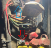
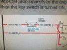
Is that wire marked 104 on the outside by any chance.? See top LH corner of the illustration in Post #40 on the previous page. The wire going out of the fuse should be 105.

I think it is the fused power supply (the fuse is visible right at the top of your photos) that feeds the key switch and the Monitor (Page 8, Grid E-3) if you follow it through the schematic. Replacing the wire and pulling the fuse should give you the same result. If that is the case my next suggestion would be to replace the fuse and unplug the Monitor Panel then see what happens
 

benbuilder

Active Member
Joined
Jan 7, 2024
Messages
32
Location
Ma
It is this one, I think 104?
(the fuse is visible right at the top of your photos) YES IT IS
fuse.jpg


I dont doubt you but is this the schematic? and which wire is it because i dont see 105-c41 RD14?

once i -(or you O) identify which wire-you want me to install a new lead rom the fuse to the back of the monitor?
 

benbuilder

Active Member
Joined
Jan 7, 2024
Messages
32
Location
Ma
I forgot to add this picture in my last post.
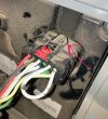
Yes i have the schematic, but i dont see where the wire - 105-c41 RD14 is in this picture at the monitorMONITOR.jpg
 

Arny L

Senior Member
Joined
Sep 23, 2020
Messages
406
Location
canada
He means put the wire that's causing the draw back in place, pull the fuse, and then go to your Monitor panel and unplug it, thereby eliminating the draw, hopefully.
 

Arny L

Senior Member
Joined
Sep 23, 2020
Messages
406
Location
canada
He means put the wire that's causing the draw back in place, pull the fuse, and then go to your Monitor panel and unplug it, thereby eliminating the draw, hopefully.
Sorry, replace wire that's causing draw. pull fuse, check draw with meter or test lamp. If its gone, unplug monitor, replace fuse
 

Nige

Senior Member
Joined
Jun 22, 2011
Messages
38,773
Location
G..G..G..Granville.........!! Fetch your cloth.
Yes i have the schematic, but i dont see where the wire - 105-c41 RD14 is in this picture at the monitor
On Page 8 of the schematic if you follow wire 105-C41 from the fuse above the Main PWR Relay to Grid H-12 you will find it goes into a splice. The wires coming out of the splice are 105-C163 and 105-C164.

1705259802244.png

Wire 105-C163 goes to CONN 15 where it becomes 105-L45 (because it is now in a different wire harness), then goes to another splice where it becomes 105-L36 (unswitched power supply to the Monitor) & 105-L62 which is the supply to the key switch.

1705259952551.png

Wire 105-C164 goes from the splice to CONN 5 where it morphs into 105-EJ5 which is the unswitched power supply to the engine ECM located at Grid D-14 on Page 9.

The ring terminal that you disconnected directly above the ECM Power relay is an unswitched supply to 3 circuits via the 15A fuse. If you ever want to kill that supply you have to turn the Master Switch OFF - assuming it works correctly that is.

1. Monitor Panel.
2. Key switch.
3. Engine ECM.
 

Arny L

Senior Member
Joined
Sep 23, 2020
Messages
406
Location
canada
On Page 8 of the schematic if you follow wire 105-C41 from the fuse above the Main PWR Relay to Grid H-12 you will find it goes into a splice. The wires coming out of the splice are 105-C163 and 105-C164.

View attachment 303074

Wire 105-C163 goes to CONN 15 where it becomes 105-L45 (because it is now in a different wire harness), then goes to another splice where it becomes 105-L36 (unswitched power supply to the Monitor) & 105-L62 which is the supply to the key switch.

View attachment 303075

Wire 105-C164 goes from the splice to CONN 5 where it morphs into 105-EJ5 which is the unswitched power supply to the engine ECM located at Grid D-14 on Page 9.

The ring terminal that you disconnected directly above the ECM Power relay is an unswitched supply to 3 circuits via the 15A fuse. If you ever want to kill that supply you have to turn the Master Switch OFF - assuming it works correctly that is.

1. Monitor Panel.
2. Key switch.
3. Engine ECM.
Great info, so you have the possibility of a draw on anyone of those circuits, however, since you had trouble initially with monitor panel, that's why were suggesting you unplug connector to monitor, and see if that's the fix. If not then, there are 2 left. Your almost there.
 

Nige

Senior Member
Joined
Jun 22, 2011
Messages
38,773
Location
G..G..G..Granville.........!! Fetch your cloth.
An extract from the notes on the schematic - the ones nobody ever bothers to read .......
The note at the bottom is the important one.
All wires should have the number printed on the outside of the insulation every 6" or so of length. So for the example below it would be a pink wire with "325" printed on the outside.

1705262634483.png
 
Last edited:

benbuilder

Active Member
Joined
Jan 7, 2024
Messages
32
Location
Ma
OK. I am excited that we are getting somewhere. I am now starting to feel a bit over my head, but last time that happened, i found the potential problem.
So i need to take my time and take the proper panels off to access these harnesses. I know inside the cab, right side. I see the schematics in the diagram Nige sent.
I wish i had the schematics on one sheet, I may do that later,
Post 69 is great info, i knew part of it.
Post 68 is confusing right now, i will study it though. If i am to replace a new wire as mentioned on post 66, I feel that the splices ay be compromised.
I think i will disconnect each circuit until i find the draw, then go from there. This may take a few days.
Thanks for all the help
 

Nige

Senior Member
Joined
Jun 22, 2011
Messages
38,773
Location
G..G..G..Granville.........!! Fetch your cloth.
Post 68 is confusing right now, i will study it though. If i am to replace a new wire as mentioned on post 66, I feel that the splices ay be compromised.
Post #68 is NOT telling you to run a NEW wire. Let me attempt to explain:-

1. Reconnect the ring terminal to the Main PWR Relay & tighten the nut - RED arrow. Pay particular attention to whether you see a spark of any kind when you reinstall the terminal or if you hear a kind of fizzing sound.
2. Remove the fuse - BLUE arrow.
3. Do you still have NO parasitic drain.? TBH nothing should change but we need to confirm.
4. If nothing changes, go to the cab and disconnect the 12-pin connector # L-C24 (illustrated below) on the back side of the Monitor Panel.
5. Replace the fuse. Check again for parasitic drain. Report your findings.

1705268392618.png1705268419006.png
 

Arny L

Senior Member
Joined
Sep 23, 2020
Messages
406
Location
canada
An extract from the notes on the schematic - the ones nobody ever bothers to read .......
The note at the bottom is the important one.
All wires should have the number printed on the outside of the insulation every 6" or so of length. So for the example below it would be a pink wire with "325" printed on the outside.
OK. I am excited that we are getting somewhere. I am now starting to feel a bit over my head, but last time that happened, i found the potential problem.
So i need to take my time and take the proper panels off to access these harnesses. I know inside the cab, right side. I see the schematics in the diagram Nige sent.
I wish i had the schematics on one sheet, I may do that later,
Post 69 is great info, i knew part of it.
Post 68 is confusing right now, i will study it though. If i am to replace a new wire as mentioned on post 66, I feel that the splices ay be compromised.
I think i will disconnect each circuit until i find the draw, then go from there. This may take a few days.
Thanks for all the help
Sorry for terminology, put ringed wire back on terminal stud. You don’t have to replace any wire
 

benbuilder

Active Member
Joined
Jan 7, 2024
Messages
32
Location
Ma
OK. I am almost have the monitor panel removed. It seems i need to remove the window or there is one other bolt keeping me from removing it. Any hints from those who have done this? Its very loos but the panel is hanging up on the window edge I have, what i think are all the window screws removed from outside, but still no movement
 

benbuilder

Active Member
Joined
Jan 7, 2024
Messages
32
Location
Ma
I dont know where you guys get this info, but i am grateful for the help. I managed to get to the back of the console display. Now to remove the plug/connection. plug rear.jpg
I moved the red (lock??) away from the display but can seem to disconnect the harness plug. Any help?
I dont want to break anything now.
EDIT- I just found a picture on line, it looks like i need to go all the way back and the hook stays with the display?
 

Attachments

  • plug rear.jpg
    plug rear.jpg
    641.9 KB · Views: 2
Last edited:

heymccall

Senior Member
Joined
Feb 19, 2007
Messages
6,156
Location
Western Pennsylvania
The depressing tab has been broken. Place small screwdriver under arrow and lift about 1/16".

The latch is still there, just the depressing ear has gone the way of the dodo.
Screenshot_20240118-173143_Chrome.jpg
 

benbuilder

Active Member
Joined
Jan 7, 2024
Messages
32
Location
Ma
I took off this plug connector, installed the fuse and checked for a parasitic drain. The test light flashed very fain and quick and that was it. No consistent light. So i guess that means its the monitor?
 
Last edited:

Nige

Senior Member
Joined
Jun 22, 2011
Messages
38,773
Location
G..G..G..Granville.........!! Fetch your cloth.
I took off this plug connector, installed the fuse and checked for a parasitic drain. The test light flashed very fain and quick and that was it. No consistent light. So i guess that means its the monitor?
It would appear so, but remove the fuse again, but this time unplug the engine ECM and repeat the test with the Monitor disconnected.
If you get no test light at all then reconnect the Monitor and repeat with the engine ECM disconnected.
 

benbuilder

Active Member
Joined
Jan 7, 2024
Messages
32
Location
Ma
The ECM, that is the part shown in post 13, where the arrow labeled 44 is?


Will do this next:
"remove the fuse again, but this time unplug the engine ECM and repeat the test with the Monitor disconnected.
If you get no test light at all then reconnect the Monitor and repeat with the engine ECM disconnected."
 
Top