
-
Thank you for visiting HeavyEquipmentForums.com! Our objective is to provide industry professionals a place to gather to exchange questions, answers and ideas. We welcome you to register using the "Register" icon at the top of the page. We'd appreciate any help you can offer in spreading the word of our new site. The more members that join, the bigger resource for all to enjoy. Thank you!
You are using an out of date browser. It may not display this or other websites correctly.
You should upgrade or use an alternative browser.
You should upgrade or use an alternative browser.
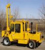
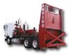
what kind of machine is this?
- Thread starter oakland
- Start date
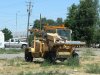
It's a hammer for breaking up pavement. The boom on the front tilts forward so it is perpendicular to the ground and the weight with the chisel is raised to the top of the boom. Then it is dropped and gravity takes over, cracking the pavement. The hammer assembly slide from right to let and back to reposition the chisel without moving the machine.
bear
Senior Member
- Joined
- Mar 22, 2008
- Messages
- 541
- Location
- South Central Kentucky
- Occupation
- Math, Physics, keeping out of trouble and doing od
Neat concept kind of like a smaller version of the machines in that other thread, (too tired and sleepy to look  ). Very little concrete roadway here I think the largest spot is about 250 ft^2. Gotta graduate and get on a real vacation to see all these interesting machines we don't have here.
). Very little concrete roadway here I think the largest spot is about 250 ft^2. Gotta graduate and get on a real vacation to see all these interesting machines we don't have here.tonka
Senior Member
We had one with a custom tool 1ft by 1ft square to do compaction in trenches. But like steve said its a old style concreet breaker. I have never seen 1 with an encosed cab before tho...
bobcatmechanic
Senior Member
they uses them with a reallly wide chisel to break run way concrete as its really thick and that one is mounted on the back of a semi tractor bobcat makes a drop hammer same concept they use 3,000lbs on theirs to get the force
The company that I worked for 17 years ago had 2 hydro hammers .They put 4' lifts and compacted the water lines in the streets . They were vary dirty and greasy and what a pain to change the cables. They had a new guy and he put 2' of dirt over a storm line and broke over 100' of pipe before he figured out he was smashing the pipe.
SPECIFICATIONS
CHASSIS: All-welded unitized frame.
ENGINE:
John Deere Powertech Series Model 4045T diesel engine. 4-cylinder, 4-cycle, 276 cubic-inch displacement (4.5 L), Bore - 4.19" (106 mm), Stroke - 5.00" (127 mm), 80 hp (60 kW) @ 2500 rpm intermittent, maximum torque of 211 lb-ft (286 Nm) @ 1700 rpm. Equipped with a full-flow oil filter and dry-type air cleaner.
TRANSMISSION:
Conventional standard, synchromesh totally enclosed transmission. Three forward speeds up to 20 mph (32 km/h) and one reverse speed.
AXLES:
Front wheel drive with single hypoid gear, axle rated at 11,500 lbs. (5,200kg). Rear wheel steering with 3,300 lbs. (1,498kg) rated axle.
CREEPER DRIVE:
Patented hydraulic creeper drive mounted directly on the transmission. Creep speed is infinitely variable up to 63 fpm (19.2 mpm) in forward or reverse.
TRANSMISSION CREEPER INTERLOCK:
Supplied with a mechanical device that prevents the creeper gear from being engaged if the travel transmission is in gear.
TIRES:
Driving tires (Dual): Load-range D - 8" x 19.5" (203 mm x 495 mm) Inflation 70 psi (482 kPa).
Steering tires: Load-range D - 8.75" x 16.5" (222 mm x 419 mm) Inflation 55 psi (379 kPa).
FENDERS:
Heavy-gauge metal fenders to provide protection of operator and vehicle from flying debris.
ROLLOVER PROTECTION STRUCTURE (ROPS)
With Seat Belts:
Rollover protection structure certified to SAE J1040 for additional operator safety.
SERVICE BRAKES: Four wheel hydraulic independent system.
PARKING BRAKE: Mechanical parking brake.
POWER STEERING:
Full power steering that allows unit to be steered when engine is not running. Steering wheel is mounted to a fixed steering column attached to the dashboard.
HORN:
Electric 12-volt horn to comply with DOT requirements.
STOP LIGHTS AND REFLECTORS:
Recessed combination stop and tail lights to comply with OSHA requirements.
FUEL TANK CAPACITY: 30 Gallons (113 L)
OIL TANK CAPACITY: 24 Gallons (91 L)
HYDRAULIC SYSTEM:
Hydraulic system consists of a tandem hydraulic pump driven directly from the engine crankshaft. The tandem hydraulic pump delivers 44 gpm (167 lpm) @ 1,750 psi (121 bar) for hammer activation and 16 gpm (61 lpm) @ 1,500 psi (103 bar) for all other functions. The system includes suction strainers, a return in-line filter and oil cooler.
HAMMER WEIGHT: 1,356 lbs. (616 kg)
IMPACT ENERGY (ft-lb): 13,000 (17680 Nm) Maximum
Click for Impact Chart
HAMMER CYCLES:
24" (.6 m) Stroke: 42 Per Minute Full Stroke: 24 Per Minute
LENGTH OF STROKE: 1' to 9' (.3 m - 2.7 m) Maximum
LEAD:
One-piece lead that lays back hydraulically for traveling/transport.
MAST TRAVERSE SYSTEM:
The mast traverse system is a hydraulically controlled chain and sprocket system that allows adjustable placement of the mast on the lead assembly. The mast traverses on long-life machine-type ways.
MAST TRAVERSE DISTANCE:
(from center line of tool) 68-1/2" (174 cm)
MAST TILT:
The mast assembly pivots hydraulically, approximately 9 degrees to either side, to provide square controllable blows.
GAUGES:
Oil Pressure, Water Temperature, Hour Meter, Fuel, and Ammeter.
ELECTRICAL SYSTEM:
12-volt system with (1) one Group 31 - 750 CCA battery and a 65 amp alternator.
OPERATOR'S AREA:
Operator's area includes controls for hammer functions (actuation, stroke control, traverse, mast tilt and mast lay-back). Also includes controls for acceleration, braking and transmission. Grip-type access steps provided for access to the seat which is adjustable front to back. Safety switches prevent engine startup if movement function controls are activated.
SHIPPING WEIGHT (Approximate): 9,600 lbs. (4,355 kg)
HEIGHT:
In working position (overall): 14'-3" (4.3 m) Traveling position with ROPS (overall): 7'-9" (2.3 m)
LENGTH:
In working position (overall): 13'-8" (4.2 m) In traveling position (overall): 14'-4" (4.4 m)
TREAD WIDTH:
Front Wheels: 84-1/2" (2146 mm) Rear Wheels: 73-1/2" (1867 mm)
WHEELBASE: 97" (2464 mm)
WIDTH (overall): 88-1/2" (2248 mm)
MAXIMUM ROAD SPEED: 20 mph (32 km/h)
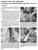
This early-production A30 was one of the mobile hydraulic drop hammers produced by Arrow, which launched the machine in 1955.Some machine innovations enjoy instant success and bring great financial rewards for their inventors. Others are ahead of their time and rapidly fade from the scene through lack of promotion or the unwillingness of customers to change traditional habits. The Arrow hydraulic hammer fits into neither of those extreme categories. The limelight never shone on this machine, and it was never exactly a household word. Yet it has survived for almost half a century, little changed from its original design, and is still hitting hard in its niche market of scoring, cutting, breaking and tamping.
The Arrow Manufacturing Co. was founded in 1943, in Denver, and produced a variety of equipment for the construction industry. In 1955, the Arrow mobile hydraulic drop hammer was introduced. This versatile self-propelled vehicle carried a hydraulically driven hammer mounted in a moveable frame. The frame could be angled or moved from side to side across the width of the machine for working close to walls or other obstructions. The operator could set the machine for manual or automatic operation. In automatic mode, he could select the height of hammer drop and speed of travel to deliver blows of uniform impact at a uniform rate. The patented hydraulically powered “creeper gear” provided working speeds up to 32 feet per minute. With the hammer frame folded down, the machine could be driven from job to job at speeds up to 30 mph.
Sales of the hammer grew worldwide and, over time, the Arrow became the industry standard for breaking concrete, compacting trench backfill, and cutting asphalt. The machine’s versatility attracted the attention of Lemand Machinery in the United Kingdom, and they began assembling the machine under license in 1963 with a British diesel engine. In 1969, Arrow C.E. Ltd, England, was granted the rights of manufacture and sales of the Arrow Hammer in Europe.
In 1975, East Moline Metal Products, a contract manufacturer based in East Moline, Ill., acquired the assets of Arrow Manufacturing Co. and moved the operation to its Moline facility, where production of the Arrow Hammer resumed. The Arrow Hammer business was conducted through EMMPCO, a wholly owned subsidiary company of East Moline Metal Products Co., until 1989 when operations were absorbed by Arrow-Master Inc. The Arrow Hammer remains a viable part of the Arrow-Master product mix to this day.
Although its basic concept and applications remain unchanged, the current Arrow Hammer, Model 1350T, has seen more than a dozen model changes since its inception in the mid-1950s. Still used by utility companies; state, county, and local municipalities; and all classes of contractors; the Arrow Hammer has survived strong competition from a wide field of hammer products introduced over the years. Its lasting popularity and longevity is a testament to its unmatched combination of high production and versatility.
SPECIFICATIONS
CHASSIS: All-welded unitized frame.
ENGINE:
John Deere Powertech Series Model 4045T diesel engine. 4-cylinder, 4-cycle, 276 cubic-inch displacement (4.5 L), Bore - 4.19" (106 mm), Stroke - 5.00" (127 mm), 80 hp (60 kW) @ 2500 rpm intermittent, maximum torque of 211 lb-ft (286 Nm) @ 1700 rpm. Equipped with a full-flow oil filter and dry-type air cleaner.
TRANSMISSION:
Conventional standard, synchromesh totally enclosed transmission. Three forward speeds up to 20 mph (32 km/h) and one reverse speed.
AXLES:
Front wheel drive with single hypoid gear, axle rated at 11,500 lbs. (5,200kg). Rear wheel steering with 3,300 lbs. (1,498kg) rated axle.
CREEPER DRIVE:
Patented hydraulic creeper drive mounted directly on the transmission. Creep speed is infinitely variable up to 63 fpm (19.2 mpm) in forward or reverse.
TRANSMISSION CREEPER INTERLOCK:
Supplied with a mechanical device that prevents the creeper gear from being engaged if the travel transmission is in gear.
TIRES:
Driving tires (Dual): Load-range D - 8" x 19.5" (203 mm x 495 mm) Inflation 70 psi (482 kPa).
Steering tires: Load-range D - 8.75" x 16.5" (222 mm x 419 mm) Inflation 55 psi (379 kPa).
FENDERS:
Heavy-gauge metal fenders to provide protection of operator and vehicle from flying debris.
ROLLOVER PROTECTION STRUCTURE (ROPS)
With Seat Belts:
Rollover protection structure certified to SAE J1040 for additional operator safety.
SERVICE BRAKES: Four wheel hydraulic independent system.
PARKING BRAKE: Mechanical parking brake.
POWER STEERING:
Full power steering that allows unit to be steered when engine is not running. Steering wheel is mounted to a fixed steering column attached to the dashboard.
HORN:
Electric 12-volt horn to comply with DOT requirements.
STOP LIGHTS AND REFLECTORS:
Recessed combination stop and tail lights to comply with OSHA requirements.
FUEL TANK CAPACITY: 30 Gallons (113 L)
OIL TANK CAPACITY: 24 Gallons (91 L)
HYDRAULIC SYSTEM:
Hydraulic system consists of a tandem hydraulic pump driven directly from the engine crankshaft. The tandem hydraulic pump delivers 44 gpm (167 lpm) @ 1,750 psi (121 bar) for hammer activation and 16 gpm (61 lpm) @ 1,500 psi (103 bar) for all other functions. The system includes suction strainers, a return in-line filter and oil cooler.
HAMMER WEIGHT: 1,356 lbs. (616 kg)
IMPACT ENERGY (ft-lb): 13,000 (17680 Nm) Maximum
Click for Impact Chart
HAMMER CYCLES:
24" (.6 m) Stroke: 42 Per Minute Full Stroke: 24 Per Minute
LENGTH OF STROKE: 1' to 9' (.3 m - 2.7 m) Maximum
LEAD:
One-piece lead that lays back hydraulically for traveling/transport.
MAST TRAVERSE SYSTEM:
The mast traverse system is a hydraulically controlled chain and sprocket system that allows adjustable placement of the mast on the lead assembly. The mast traverses on long-life machine-type ways.
MAST TRAVERSE DISTANCE:
(from center line of tool) 68-1/2" (174 cm)
MAST TILT:
The mast assembly pivots hydraulically, approximately 9 degrees to either side, to provide square controllable blows.
GAUGES:
Oil Pressure, Water Temperature, Hour Meter, Fuel, and Ammeter.
ELECTRICAL SYSTEM:
12-volt system with (1) one Group 31 - 750 CCA battery and a 65 amp alternator.
OPERATOR'S AREA:
Operator's area includes controls for hammer functions (actuation, stroke control, traverse, mast tilt and mast lay-back). Also includes controls for acceleration, braking and transmission. Grip-type access steps provided for access to the seat which is adjustable front to back. Safety switches prevent engine startup if movement function controls are activated.
SHIPPING WEIGHT (Approximate): 9,600 lbs. (4,355 kg)
HEIGHT:
In working position (overall): 14'-3" (4.3 m) Traveling position with ROPS (overall): 7'-9" (2.3 m)
LENGTH:
In working position (overall): 13'-8" (4.2 m) In traveling position (overall): 14'-4" (4.4 m)
TREAD WIDTH:
Front Wheels: 84-1/2" (2146 mm) Rear Wheels: 73-1/2" (1867 mm)
WHEELBASE: 97" (2464 mm)
WIDTH (overall): 88-1/2" (2248 mm)
MAXIMUM ROAD SPEED: 20 mph (32 km/h)
This early-production A30 was one of the mobile hydraulic drop hammers produced by Arrow, which launched the machine in 1955.Some machine innovations enjoy instant success and bring great financial rewards for their inventors. Others are ahead of their time and rapidly fade from the scene through lack of promotion or the unwillingness of customers to change traditional habits. The Arrow hydraulic hammer fits into neither of those extreme categories. The limelight never shone on this machine, and it was never exactly a household word. Yet it has survived for almost half a century, little changed from its original design, and is still hitting hard in its niche market of scoring, cutting, breaking and tamping.
The Arrow Manufacturing Co. was founded in 1943, in Denver, and produced a variety of equipment for the construction industry. In 1955, the Arrow mobile hydraulic drop hammer was introduced. This versatile self-propelled vehicle carried a hydraulically driven hammer mounted in a moveable frame. The frame could be angled or moved from side to side across the width of the machine for working close to walls or other obstructions. The operator could set the machine for manual or automatic operation. In automatic mode, he could select the height of hammer drop and speed of travel to deliver blows of uniform impact at a uniform rate. The patented hydraulically powered “creeper gear” provided working speeds up to 32 feet per minute. With the hammer frame folded down, the machine could be driven from job to job at speeds up to 30 mph.
Sales of the hammer grew worldwide and, over time, the Arrow became the industry standard for breaking concrete, compacting trench backfill, and cutting asphalt. The machine’s versatility attracted the attention of Lemand Machinery in the United Kingdom, and they began assembling the machine under license in 1963 with a British diesel engine. In 1969, Arrow C.E. Ltd, England, was granted the rights of manufacture and sales of the Arrow Hammer in Europe.
In 1975, East Moline Metal Products, a contract manufacturer based in East Moline, Ill., acquired the assets of Arrow Manufacturing Co. and moved the operation to its Moline facility, where production of the Arrow Hammer resumed. The Arrow Hammer business was conducted through EMMPCO, a wholly owned subsidiary company of East Moline Metal Products Co., until 1989 when operations were absorbed by Arrow-Master Inc. The Arrow Hammer remains a viable part of the Arrow-Master product mix to this day.
Although its basic concept and applications remain unchanged, the current Arrow Hammer, Model 1350T, has seen more than a dozen model changes since its inception in the mid-1950s. Still used by utility companies; state, county, and local municipalities; and all classes of contractors; the Arrow Hammer has survived strong competition from a wide field of hammer products introduced over the years. Its lasting popularity and longevity is a testament to its unmatched combination of high production and versatility.
Attachments
oakland
COPPA
wow! i didnt think i would get that much information on it thankyou so much.
Wolverine69
Member
There's a guy here in the St. Charles, MO area that has one of those concrete busters that he hauls around on the back of an old school bus that he's converted into a flat bed truck with ramps.
kpower42
New Member
pavement breaker
in the uk these are called arrow breakers they are very good on concrete up to 9"thick thay are fully automatic
this machine was in pocatello idaho never once saw it move or where it was working at i was hoping someone could tell me what it is.
in the uk these are called arrow breakers they are very good on concrete up to 9"thick thay are fully automatic
digger242j
Administrator
As opposed to a breaker mounted on a hoe or excavator, which is sometimes called a hoe-ram, I've heard these machines referred to as a "Hy-ram".
I've seen one used to compact a waterline trench, but that was a good 40+ years ago. (Yes, I was a little kid.) I haven't seen one in the field for a few years now, but one guy I know that's had one swears by them.
I've seen one used to compact a waterline trench, but that was a good 40+ years ago. (Yes, I was a little kid.) I haven't seen one in the field for a few years now, but one guy I know that's had one swears by them.
kpower42
New Member
arrow breaker
filled in for a guy who was sick for 3 days i think it was a 402? perkins eng. rig leaked oil bad.the firm i worked for had about 6. driver had to repair himself.wire rope allways breaking it was running on the same place on the sheath nearly all the time. memory nearly gone rear wheel steering. no lowboy ken
filled in for a guy who was sick for 3 days i think it was a 402? perkins eng. rig leaked oil bad.the firm i worked for had about 6. driver had to repair himself.wire rope allways breaking it was running on the same place on the sheath nearly all the time. memory nearly gone rear wheel steering. no lowboy ken
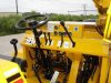
Thought I would bring this topic back up, qball and I were talking about these machines today. Antigo construction out of Antigo, Wisconsin. http://www.antigoconstruction.com/index.html These are really cool machines, we don't see them much around here. Take a look through the site, it shows all the processes. Very cool, thanks qball.:drinkup
Attachments
albertrichard
New Member
Nice pictures. What is the market price of such hammers?
kpower42
New Member
arrow breaker
albertrichard. i have no idea what they would cost.it has been 36 years sense i operated one i would think about £ 500 ken/
albertrichard. i have no idea what they would cost.it has been 36 years sense i operated one i would think about £ 500 ken/
VoodooMojo
Senior Member
- Joined
- Jan 18, 2012
- Messages
- 344
- Location
- Baltimore, East Coast USA
- Occupation
- Sr Technical Service Representative
Broderson (Lenexa Kansas) had a Hydra-Hammer also.
I don't know if they still produce it.
Here is a video of one in action:
http://www.youtube.com/watch?v=648IyPSbkKo
I don't know if they still produce it.
Here is a video of one in action:
http://www.youtube.com/watch?v=648IyPSbkKo
