• Thank you for visiting HeavyEquipmentForums.com! Our objective is to provide industry professionals a place to gather to exchange questions, answers and ideas. We welcome you to register using the "Register" icon at the top of the page. We'd appreciate any help you can offer in spreading the word of our new site. The more members that join, the bigger resource for all to enjoy. Thank you!

TL130 Fuel Stop Solenoid

drummer0901

Active Member
Joined
Feb 17, 2019
Messages
36
Location
TN
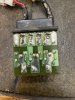
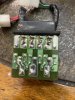
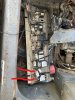
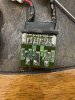
I have a 2004 TL130 that I have been dealing with for some time. Like many of the threads I have ready, I am not getting power to the red wire of the stop solenoid. I have continuity from the red wire on the K relay to the red wire at the fuel stop relay, but no power coming from the that pin. I do have switched power on the yellow pin (#3) and the White wire at the relay. I replaced the "K" relay thinking that may be the problem, but have the same issue.

Anyone have insight as to what powers the red wire?
 

James alex zheltonoga

Well-Known Member
Joined
Jan 5, 2023
Messages
48
Location
8214 easton road ottsville pa. 18942
Hey Drummer, I have been having the same problem with my Gehl ctl80. I bought the manual online to get the wiring diagram. When i got it it was printed so bad i had to get it enlarged at staples.
I had some diagrams sent to me from heymccall on equipment forums, and they were very good prints. I still have not figured mine out yet just wanted to let you know about bad factory wiring diagrams. Dont waste your money on them. Maybe heymccall will read this and post a link to the diagram that he has.
 

ahart

Senior Member
Joined
Nov 7, 2020
Messages
837
Location
Indiana
I believe I have the service manual on a jump drive in my truck, I’ll check tomorrow and see.
 

heymccall

Senior Member
Joined
Feb 19, 2007
Messages
5,385
Location
Western Pennsylvania
Standard answer when the hold wire doesn't energize...resolder all the cold solder joints in the two triple relays. None of the other relays are suspect, nor do any of the ogher relays easily disassemble.
Screenshot_20230213-210355_Drive.jpg

Below is full schematic. As far as I'm concerned, it is the same as a TL130.
 

Attachments

  • TL150 Electrical.pdf
    153.1 KB · Views: 7

James alex zheltonoga

Well-Known Member
Joined
Jan 5, 2023
Messages
48
Location
8214 easton road ottsville pa. 18942
I still dont understand where it says relay unit 3 (relay,3) if that is one of those three relays inside of The J or K relays ? I see a D1,D2 and a D3 on the board under the three little white relays when you take the cover off of the BE31-107 relay. I am thinking these are the ones ,but the wire colors going to them dont match up with the wiring diagram.
 

drummer0901

Active Member
Joined
Feb 17, 2019
Messages
36
Location
TN
I have pdfs of the service manual that I can blow up. I have tested the stop solenoid and it works as expected. I have continuity from the emergency relay to the stop solenoid timer, but the relay is not energizing that circuit, it’s a new relay. I haven’t taken the relay apart yet. I did find the light green wire in the horn circuit to be corroded and waiting on some terminals to put it back together. My fear is it’s the gauge cluster relays. Does anyone know how to test the relays to verify they are working correctly?
 

drummer0901

Active Member
Joined
Feb 17, 2019
Messages
36
Location
TN
Sorry about that I am talking about the hold, I meant I have continuity from Relay L to the stop solenoid
YZiIYobio
W8JgHOKNku
its not a broken wire. White wire functions as expected

I have power on the pink wire going into the relay L

I have 1 new reley, and both old ones and cant see any visible cracks in the solder on any of them.
 

Attachments

  • IMG_3711.jpg
    IMG_3711.jpg
    1.8 MB · Views: 24
  • IMG_3710.jpg
    IMG_3710.jpg
    1.8 MB · Views: 21
  • InkedIMG_3674.jpg
    InkedIMG_3674.jpg
    3.8 MB · Views: 22

drummer0901

Active Member
Joined
Feb 17, 2019
Messages
36
Location
TN
Here you go. Would love to know how to bench test these.
 

Attachments

  • IMG_3713.jpg
    IMG_3713.jpg
    101.6 KB · Views: 15
  • IMG_3712.jpg
    IMG_3712.jpg
    2.4 MB · Views: 14

drummer0901

Active Member
Joined
Feb 17, 2019
Messages
36
Location
TN
I will look at these under magnification. May just buy another new one, just to be safe. Is there a way to rule out the gauge cluster?
 

drummer0901

Active Member
Joined
Feb 17, 2019
Messages
36
Location
TN
Thank you for this! I ordered a second new relay, and while I'm waiting on it, I'll try to fix these. Crossing my fingers!
 

drummer0901

Active Member
Joined
Feb 17, 2019
Messages
36
Location
TN
Still waiting on the 2nd relay, but I went thru all the solder joints on both of these relays, swapped in the 1 new one in both locations and the behavior didnt change at all, no hold in circuit.

New revelation, I now have mementary power to the pull in circuit when the key first turns on, it then turns off. But no power during cranking. I am assuming stop solenoid relay has power (yellow) coming in and should have power on the white during cranking?

I still can't get power for the hold circuit (Red) on Relay L. I've read pin 1 (Bottom right-no wire attached on this pin) is powered with key on. Power jumps to pin 5 during cranking. Am I reading the pins correctly? Seems like I have read the hold in circuit should be hot with key on.

I did test both emergency stop relays and they tested good in the cluster.
 

drummer0901

Active Member
Joined
Feb 17, 2019
Messages
36
Location
TN
I’ve read the relays are on the logic board, I have 2 4 pin relays mounted just under the cover, tested both, they have resistance less than 100 and click when power applies. I’m assuming these are the emergency relays.
 
Top