-
Thank you for visiting HeavyEquipmentForums.com! Our objective is to provide industry professionals a place to gather to exchange questions, answers and ideas. We welcome you to register using the "Register" icon at the top of the page. We'd appreciate any help you can offer in spreading the word of our new site. The more members that join, the bigger resource for all to enjoy. Thank you!
You are using an out of date browser. It may not display this or other websites correctly.
You should upgrade or use an alternative browser.
You should upgrade or use an alternative browser.
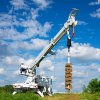
My long quest for water... A homemade well drilling rig. Have you ever done this?
- Thread starter Georgia Iron
- Start date
crane operator
Senior Member
Really any heavy 90 degree gearbox would work, hydraulic drive in, and the gearbox bearings taking the thrust off the drill drive.
Georgia Iron
Senior Member
- Joined
- May 6, 2012
- Messages
- 878
- Location
- USA - Georgia
- Occupation
- Concrete building slab and grading contractor
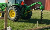
I have a skid steer auger. I might use it if I can not get the swing motor to work..How about a skid steer auger drive motor? Then when you're done you can put it back to skid steer use, sell it and get your money back.
Georgia Iron
Senior Member
- Joined
- May 6, 2012
- Messages
- 878
- Location
- USA - Georgia
- Occupation
- Concrete building slab and grading contractor
Georgia Iron
Senior Member
- Joined
- May 6, 2012
- Messages
- 878
- Location
- USA - Georgia
- Occupation
- Concrete building slab and grading contractor
I decided to use some used pallet racks as the frame for the mast. I went back and forth between that and a big steel I-Beam. Being that the cylinder can extend 14 feet, and that I needed area to attach other items to I wanted a little wider frame work to be able to work off of. I decided that about 2 feet of width would be about right.
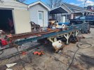
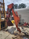
In this photo you can see the drill motor mount that was cut loose from the boom, and you can see the boom pivot assembly being placed on to the frame work.
I have to cut and redo this several times to get it where it needed to be.
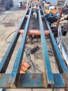
In this photo, I have set in the mast hydraulic cylinder. In placing the cylinder, I was mostly worried about how to balance an offset load so that it could not place a side force onto the extended cylinder.
I decided that I would need the cylinder to follow the rear rails while the drill follows the front frame work...
In simple terms the cylinder justs needs to provide a linear force... you cannot use the cylinder to support a side load. The frame work must carry the load and the cylinder is only used to push or pull it in a straight line.
An issue I have is the cylinder is about 10' long and it extends another 14 feet, so you need 25 feet or more of mast length... I have only have 18 feet unless I decide to extend the mast frame work...
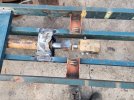
I cut out the cylinder mounting bracket from the boom and used it to mount the cylinder to the mast frame work. I also torch cut the ears off the second stage of the hydraulic...

In this photo you can see the drill motor mount that was cut loose from the boom, and you can see the boom pivot assembly being placed on to the frame work.
I have to cut and redo this several times to get it where it needed to be.

In this photo, I have set in the mast hydraulic cylinder. In placing the cylinder, I was mostly worried about how to balance an offset load so that it could not place a side force onto the extended cylinder.
I decided that I would need the cylinder to follow the rear rails while the drill follows the front frame work...
In simple terms the cylinder justs needs to provide a linear force... you cannot use the cylinder to support a side load. The frame work must carry the load and the cylinder is only used to push or pull it in a straight line.
An issue I have is the cylinder is about 10' long and it extends another 14 feet, so you need 25 feet or more of mast length... I have only have 18 feet unless I decide to extend the mast frame work...

I cut out the cylinder mounting bracket from the boom and used it to mount the cylinder to the mast frame work. I also torch cut the ears off the second stage of the hydraulic...
Last edited:
Georgia Iron
Senior Member
- Joined
- May 6, 2012
- Messages
- 878
- Location
- USA - Georgia
- Occupation
- Concrete building slab and grading contractor
Looking down the mast from the front side.
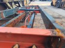
Working on the height, balance and correct center point for the pivot pin assembly. And getting every weld I can get on it while it is still on the ground..
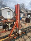
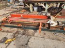
Since I was using some parts that were already made for another application, I had to make it work with what I had. As you can see, I am not going clean every torch cut and make it pretty, I just want it to be strong and for it to work. My spare days working on this are flying by.. Mostly only get rainy days to work on it.
The sheer size of the mast and weight make it hard to move around and be able to weld all places. I turned it over and got everything from the top and bottom and will get the rest once it is standing up.
Our forklift is now having problems moving it around due to the weight and length of it. It needs an overhead crane but don't have one.
In testing where to put the pivot, I had to determine how much length would be needed to get the mast to pivot off the front of the ditch witch and I needed the pivot to be in the center of the load....
I was able to use a single chain with the lift to locate the load center and went from there.

Working on the height, balance and correct center point for the pivot pin assembly. And getting every weld I can get on it while it is still on the ground..


Since I was using some parts that were already made for another application, I had to make it work with what I had. As you can see, I am not going clean every torch cut and make it pretty, I just want it to be strong and for it to work. My spare days working on this are flying by.. Mostly only get rainy days to work on it.
The sheer size of the mast and weight make it hard to move around and be able to weld all places. I turned it over and got everything from the top and bottom and will get the rest once it is standing up.
Our forklift is now having problems moving it around due to the weight and length of it. It needs an overhead crane but don't have one.
In testing where to put the pivot, I had to determine how much length would be needed to get the mast to pivot off the front of the ditch witch and I needed the pivot to be in the center of the load....
I was able to use a single chain with the lift to locate the load center and went from there.
Last edited:
Georgia Iron
Senior Member
- Joined
- May 6, 2012
- Messages
- 878
- Location
- USA - Georgia
- Occupation
- Concrete building slab and grading contractor
Today is another rain day...
At this point in the project. The mast is ready to be mocked up and mounted to the frame. I brought over a skid steer with a set of forks to help speed up turning the mast over and getting it in the right spot.
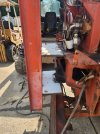
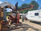
The ditch witch had a dozer blade on it. I did not want the frame work to stop the blade from being able to be used. I also had to keep the frame work up high so that the trailer approach angle could still work. It wants to drag on the front edge.
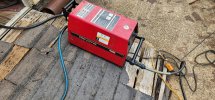
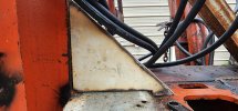
My pro cut 55, I got it used. One of my favorite tools.. You can quickly widdle down steel to fit in strange shapes. This looks like a tri-angle plate and it is but is has a slight backwards lean. Nice tight fits.. Easy to weld.
At this point in the project. The mast is ready to be mocked up and mounted to the frame. I brought over a skid steer with a set of forks to help speed up turning the mast over and getting it in the right spot.


The ditch witch had a dozer blade on it. I did not want the frame work to stop the blade from being able to be used. I also had to keep the frame work up high so that the trailer approach angle could still work. It wants to drag on the front edge.

My pro cut 55, I got it used. One of my favorite tools.. You can quickly widdle down steel to fit in strange shapes. This looks like a tri-angle plate and it is but is has a slight backwards lean. Nice tight fits.. Easy to weld.

Last edited:
Georgia Iron
Senior Member
- Joined
- May 6, 2012
- Messages
- 878
- Location
- USA - Georgia
- Occupation
- Concrete building slab and grading contractor
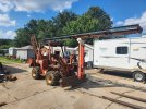
Mast is mounted up. You could use one hand and 3 fingers to raise or lower the mast. Almost seemed like magic for it pivot.
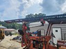
Next it is on to my tilt cylinder. It was interesting figuring out where to place it and how. A lot of guys have had to do something similar making a trailer dump bed. This could give you an idea on how to mount a hydraulic cylinder to achieve a 90* degree movement. On a trailer you can set it in much closer or even inside the frame work.
This cylinder was taken off the boom and was the cylinder that would raise and lower the boom angle. It is about 48" in length and around a 4" shaft diameter. The cylinder location had to allow a lot of other movement of steel so that it did not interfere with my mast cylinder movement, the drill movement, the line winch, and hydraulic control panel.
Looking at the mast it is seems to need a large cylinder to move it but it does not and this cylinder is overkill. It was part of what I got off the boom and the length worked out nicely.
Last edited:
Georgia Iron
Senior Member
- Joined
- May 6, 2012
- Messages
- 878
- Location
- USA - Georgia
- Occupation
- Concrete building slab and grading contractor
Georgia Iron
Senior Member
- Joined
- May 6, 2012
- Messages
- 878
- Location
- USA - Georgia
- Occupation
- Concrete building slab and grading contractor
Now I want to mount my line winch. I also am figuring out hydraulic line placement and some hose lengths for my different cylinders.
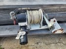
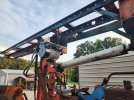
I wanted something that could help handle casing weight. This unit has rated 1000 lb or so capacity with the rope and steel wire inside. Another boom takeoff.
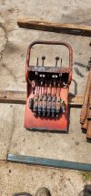
At this point 6 hydraulic functions, are being used.
1. Mast tilt
2. Winch
3. Drill up and down
4. Drill turn
5. Left stabilizer.
6. Right stabilizer.
7. I am out of spools...
Last edited:
Georgia Iron
Senior Member
- Joined
- May 6, 2012
- Messages
- 878
- Location
- USA - Georgia
- Occupation
- Concrete building slab and grading contractor
Georgia Iron
Senior Member
- Joined
- May 6, 2012
- Messages
- 878
- Location
- USA - Georgia
- Occupation
- Concrete building slab and grading contractor
After several days over many weeks thinking about how I could protect and keep my main lift hydraulic cylinder from destroying itself with too much down or up pressure causing the frame to buckle and/or the cylinder to bend. I came up with an assembly that would travel and would support the drill with multiple connection points to help balance the load across the framework.
The drill is going to slide on the rails on a carraige. Here I am drilling some mounting holes for the outside carraige.
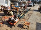
The assembly is made in 3 parts. Drill carriage, lift cylinder carriage, and a connection between the 2 that allows for height change.
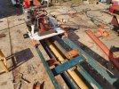
This is part of the upper carraige for the lift cylinder.
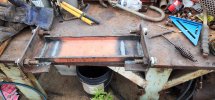
I bought a few 10 packs of 3/4" shaft diameter sealed roller bearings off of amazon
to help it move along the framework. These fit the common bolt size of 3/4", the bearings are rated for about 2000lbs each. I have a 5 gallon bucket of bolts and washers which easliy allow me to change the spacing. As hard as I tried to weld the mast frame to the same width it varied just a little due to the welds pulling it in in places.
The carraige could have moved on just a metal to metal fit and slide with grease but I wanted it to roll freely if I get too much down pressure.
The drill is going to slide on the rails on a carraige. Here I am drilling some mounting holes for the outside carraige.

The assembly is made in 3 parts. Drill carriage, lift cylinder carriage, and a connection between the 2 that allows for height change.

This is part of the upper carraige for the lift cylinder.

I bought a few 10 packs of 3/4" shaft diameter sealed roller bearings off of amazon
to help it move along the framework. These fit the common bolt size of 3/4", the bearings are rated for about 2000lbs each. I have a 5 gallon bucket of bolts and washers which easliy allow me to change the spacing. As hard as I tried to weld the mast frame to the same width it varied just a little due to the welds pulling it in in places.
The carraige could have moved on just a metal to metal fit and slide with grease but I wanted it to roll freely if I get too much down pressure.
Last edited:
Georgia Iron
Senior Member
- Joined
- May 6, 2012
- Messages
- 878
- Location
- USA - Georgia
- Occupation
- Concrete building slab and grading contractor
Here is the top carraige assembly from the front view, extended.
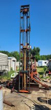
This photo shows the rear sliding top carriage, front of the top carriage and the lower drill carriage / mount and connector bar installed. The connector bar can change the resting height of the drill motor.
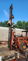
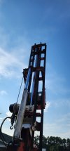
A rear shot of the upper carriage.

This photo shows the rear sliding top carriage, front of the top carriage and the lower drill carriage / mount and connector bar installed. The connector bar can change the resting height of the drill motor.


A rear shot of the upper carriage.
Georgia Iron
Senior Member
- Joined
- May 6, 2012
- Messages
- 878
- Location
- USA - Georgia
- Occupation
- Concrete building slab and grading contractor
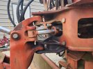
The 4010 had serveral cylinders that required repacking. So far 6 in total. The cylinders use the retaining ring that comes out as you turn the gland. One in particular had stripped the hole out of the gland so the ring did not want to come out as you turn the end. After serveral hours of work I was able to get the ring with plyers and got it out. Thought it was going to ruin the end of the cylinder.
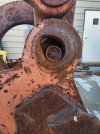
On several of the retaining pins they had rusted into place. A torch and a hydraulic press was used to remove them. Had to weld a make shift frame to flanges to hold the porta-power cylinder next to the pin bushings. Also had to weld the tabs on each side of the cylinder together with supports so that the porta-power did not bend the flanges.
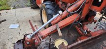
On several of the retaining pins they had rusted into place. A torch and a hydraulic press was used to remove them. Had to weld a make shift frame to flanges to hold the porta-power cylinder next to the pin bushings. Also had to weld the tabs on each side of the cylinder together with supports so that the porta-power did not bend the flanges.

Last edited:
Georgia Iron
Senior Member
- Joined
- May 6, 2012
- Messages
- 878
- Location
- USA - Georgia
- Occupation
- Concrete building slab and grading contractor
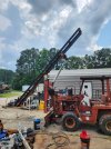
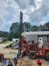
Went ahead a loaded up a few thousand pounds to test out the lift cylinder and to check for flexing or missing or bad welds. The hydraulic system lifted this load without any change in motor rpm on idle.
The frame and mounts did not move or flex. The carriage moves smoothly up and down. The lift cylinder has safeties in it that will not allow it to move unless it has hydraulic pressure... If you blow a hose or turn off the machine you cannot lower or raise the lift...
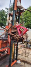
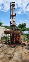
Also checking cylinder lift speed, and general function.
This brings me up to current progress on the rig work.
Next will be:
1. Mounting the drill motor and hydraulic lines.
2. Building a housing to protect the motor from up and down stress.
3. I need to build a drill stem guide and table, with hydraulic clamp.
4. To build a lower mast lock which will allow me to trim it into level with the cylinder and then lock the mast level to the lower portion of the frame assembly. I do not want to rely on the hydraulic cylinder to hold it on level while drilling.
5. I need to build an auger end for the drill. Size not sure about.
6. I need to build a mast head and guide for the winch line.
7. I need to plumb in for the hydraulic clamp..
Then further testing to check down pressure and drill speeds. I am considering installing pressure gauges to monitor the down force and drill turn force.
The frame and mounts did not move or flex. The carriage moves smoothly up and down. The lift cylinder has safeties in it that will not allow it to move unless it has hydraulic pressure... If you blow a hose or turn off the machine you cannot lower or raise the lift...


Also checking cylinder lift speed, and general function.
This brings me up to current progress on the rig work.
Next will be:
1. Mounting the drill motor and hydraulic lines.
2. Building a housing to protect the motor from up and down stress.
3. I need to build a drill stem guide and table, with hydraulic clamp.
4. To build a lower mast lock which will allow me to trim it into level with the cylinder and then lock the mast level to the lower portion of the frame assembly. I do not want to rely on the hydraulic cylinder to hold it on level while drilling.
5. I need to build an auger end for the drill. Size not sure about.
6. I need to build a mast head and guide for the winch line.
7. I need to plumb in for the hydraulic clamp..
Then further testing to check down pressure and drill speeds. I am considering installing pressure gauges to monitor the down force and drill turn force.
Last edited:
Welder Dave
Senior Member
Is that an MF135 (diesel) in the background?
Georgia Iron
Senior Member
- Joined
- May 6, 2012
- Messages
- 878
- Location
- USA - Georgia
- Occupation
- Concrete building slab and grading contractor
Good eye. Yes it is.Is that an MF135 (diesel) in the background?
Welder Dave
Senior Member
I have a UK model with Multi-Power. Most reliable machine I own and it's a 1st year UK 1965 model. Sips fuel is an understatement.
Georgia Iron
Senior Member
- Joined
- May 6, 2012
- Messages
- 878
- Location
- USA - Georgia
- Occupation
- Concrete building slab and grading contractor
I also have a mf165, it has foam filled front tires and 6' bush hog. You are correct about the 135 fuel usage. Mine has lost the pto lift and I need to repair it. If I could only find the time.

