• Thank you for visiting HeavyEquipmentForums.com! Our objective is to provide industry professionals a place to gather to exchange questions, answers and ideas. We welcome you to register using the "Register" icon at the top of the page. We'd appreciate any help you can offer in spreading the word of our new site. The more members that join, the bigger resource for all to enjoy. Thank you!

John Deere 219 engine: trouble starting after rebuild

pjflyer

Well-Known Member
Joined
Mar 27, 2012
Messages
127
Location
Wolverine, MI
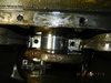
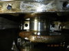
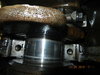
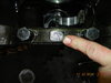
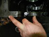
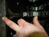
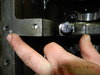
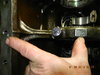
We don't have the tool, I think it's JD 234 or something, but looking at the pictures it lines up with the center of the crank. So we took a straight edge and went center of crank to center of shaft of whatever is being timed and put the timing mark along that line. The tool looks like a Y.

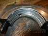
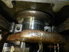
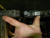
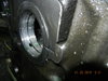
That brings up a question we had about the balancers. The book said to mark them left or right before you take them out, but no way to id them otherwise. We got the engine dismantled and they weren't marked left or right. Both of them have the same numbers and no left or right designation. They have the timing marks on the gear. They can go one of two ways. If the timing marks are aligned with the crank, does it matter which way they go?? Or is it that as long as they are spinning counter opposed the important part??
 

rondig

Senior Member
Joined
Jul 24, 2013
Messages
517
Location
fort macleod alberta
Occupation
excavation
Yeah the higher rpm sounds like motor was too tight causing governor to stroke pump....caps going on backwards is not right at all...did you lube liner seals before putting them in? Do not use oil as they will swell. Also i use bearing floss...looks like dental floss...it measure bearing clearance when torqued. Also if caps didnt fit...sounds like line bore was not done...i would always line bore on an unknown engine.
 

mg2361

Senior Member
Joined
Jul 5, 2016
Messages
5,156
Location
Pennsylvania
Occupation
Equipment Mechanic
With #1 piston top dead center on compression the weights should be straight down. There used to be an "L" or "R" stamped on the back of the balancer behind the last journal. They are different art numbers.
 

pjflyer

Well-Known Member
Joined
Mar 27, 2012
Messages
127
Location
Wolverine, MI
We didn't use any lube on the liners just slid them in. Good to know about the balancers, I'll check again for l or r, but the straight down part we can make sure of. And then mark them!!
 
  • Like
Reactions: DB2

pjflyer

Well-Known Member
Joined
Mar 27, 2012
Messages
127
Location
Wolverine, MI
Ok....Who's the winner? After pulling the engine and pulling off the oil pan, it was obvious it was the last bearing causing the issue. The crank was pushed forward and whatever the piece that the flywheel bolts to is called, was rubbing on the thrust portion of the back bearing (#5). We didn't get the crank pulled out yet, but with #5 bearing cap removed, the crank spun fine. I'm not sure what how bad the damage is to anything, but so far it seems contained to the bearing. Here are pics of the oil pan with shavings, #5 cap, and the crank still in the block. We were able to tap the crank forward. When we first pulled it apart, the bearing and back of the crank were touching.

We think we probably bumped the crank on the spline while putting the engine in. We don't recall it bumping or it hitting hard, but with the weight of the engine, it probably doesn't take much to move it (the crank). Which brings up the question of if we did bump it, would it stay there or work away from where it's touching and binding? Or what else would've caused it? DSCN1357.JPG
 

Attachments

  • DSCN1358.JPG
    DSCN1358.JPG
    227.6 KB · Views: 47
  • DSCN1350.JPG
    DSCN1350.JPG
    243.3 KB · Views: 50
  • DSCN1351.JPG
    DSCN1351.JPG
    242.6 KB · Views: 50

pjflyer

Well-Known Member
Joined
Mar 27, 2012
Messages
127
Location
Wolverine, MI
More pics.
 

Attachments

  • DSCN1352.JPG
    DSCN1352.JPG
    232.8 KB · Views: 53
  • DSCN1353.JPG
    DSCN1353.JPG
    232.4 KB · Views: 51
  • DSCN1354.JPG
    DSCN1354.JPG
    230.7 KB · Views: 52
  • DSCN1356.JPG
    DSCN1356.JPG
    230.6 KB · Views: 54

BigWrench55

Senior Member
Joined
Oct 11, 2018
Messages
1,176
Location
Somewhere
Could you load pictures of the rest of the main caps? It looks to me that you have one swapped. The picture of the block side shows a thrust bearing and the main cap picture doesn't have a thrust bearing in it. Either the bearing is in the wrong place on the block or the wrong main cap is installed. 20190125_230704.jpg 20190125_231031.jpg 20190125_230704.jpg
 

pjflyer

Well-Known Member
Joined
Mar 27, 2012
Messages
127
Location
Wolverine, MI
Now that you mention it, I know what you mean. I'll get more pics tomorrow as we get it apart. I will also try to pics of how the caps line up with the block. Looking at these pics I'm getting myself confused!!
 

farmerlund

Senior Member
Joined
Nov 22, 2014
Messages
1,237
Location
North Dakota
Occupation
Farmer/ excavator
I agree with Paul. The thrust bearing should go all the way around, not just 180 degrees. plus thrust main caps are different then the rest. You must have the other half of thrust bearing in the wrong location also. lucky it didn't run long.:eek:
 

mg2361

Senior Member
Joined
Jul 5, 2016
Messages
5,156
Location
Pennsylvania
Occupation
Equipment Mechanic
Take note that when you have the proper caps in the proper place and you install the thrust bearing and it's cap Deere's procedure says to install thrust cap hand tight then tap crank towards the rear (use a dead blow, not a steel hammer), then tap crank towards the front then tighten the bearing cap (see highlighted text in attachment). Then check your end play. It should be 0.002" - 0.015". Make sure when you install engine you still have crank end play and that something external is not "pushing" the crank front. Also if you would please, post a picture of the number side of the main caps.
 

Attachments

  • 440A Thrust bearing.pdf
    643.5 KB · Views: 7

pjflyer

Well-Known Member
Joined
Mar 27, 2012
Messages
127
Location
Wolverine, MI
I see in the picture it's hard to see the flange on the outer part of the cap. I will get more pics up later today. We also did tap the crank both directions to set the thrust bearing before we torqued the caps, that's why we were thinking something moved the crank forward either during or after the install. It's hard to see the stamped numbers on the caps, but I'll try to get at an angle where it shows up. These were the caps that came with this block and engine. I see what a nightmare it is getting an engine that has already been torn down.
 

56wrench

Senior Member
Joined
Dec 4, 2016
Messages
2,127
Location
alberta
in the picture of the #5 main journal, the fillet radius of the crank does not appear to match the bearing. so either the thrust bearing is in another location, the crank is not properly reground or the crank is wrong for that block. were all the upper bearing shells installed with the oil holes lined up properly? usually, the lower shells don't have oil holes in them
 

pjflyer

Well-Known Member
Joined
Mar 27, 2012
Messages
127
Location
Wolverine, MI
I now have a question as far as matching up the stamped numbers. Are they supposed to line up if the engine was split in half left to right or front to back. If it's front to back the numbers align.
All of the bearings had oil holes in them. I'm attaching several pics.
Here is the order of pics:
Number on cap #1
Numbers are at my finger tip and tip of thumb which are hard to see. I couldn't get at any better angle.
In order #1 through #5
#5 bearing outside of block - 2 pics
#5 bearing inside of block
next 4 are of the caps with bearings in without the crank. I see #2 wasn't all the way down, but it does go.
#5 bearing slot without the bearing outside the block
#5 bearing slot without the bearing inside the block
#5 thrust bearing removed.
 

Attachments

  • DSCN1360.JPG
    DSCN1360.JPG
    213.1 KB · Views: 31
  • DSCN1361.JPG
    DSCN1361.JPG
    225.2 KB · Views: 30
  • DSCN1362.JPG
    DSCN1362.JPG
    218.8 KB · Views: 30
  • DSCN1363.JPG
    DSCN1363.JPG
    223 KB · Views: 33

pjflyer

Well-Known Member
Joined
Mar 27, 2012
Messages
127
Location
Wolverine, MI
more pics
 

Attachments

  • DSCN1364.JPG
    DSCN1364.JPG
    224 KB · Views: 22
  • DSCN1365.JPG
    DSCN1365.JPG
    226.9 KB · Views: 22
  • DSCN1368.JPG
    DSCN1368.JPG
    240.8 KB · Views: 23
Top