• Thank you for visiting HeavyEquipmentForums.com! Our objective is to provide industry professionals a place to gather to exchange questions, answers and ideas. We welcome you to register using the "Register" icon at the top of the page. We'd appreciate any help you can offer in spreading the word of our new site. The more members that join, the bigger resource for all to enjoy. Thank you!

Hydraulic Problem With Pilot Controls

OCR

Senior Member
Joined
Feb 21, 2008
Messages
1,195
Location
Montana
Occupation
Rancher/Farmer, Wildland Fire Fighter, State snowp
Problem With Pilot Controls:

I know nothing... lol

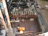
Oops, what I meant to say was; and it is hard to tell from the picture, but on some systems, they incorporate a valve to release the pressure manually, ie... engine failure, or something that causes the pilots to not function.

My Cat 312 BL has this feature, it's called the "manual boom let down valve", or pretty close to that any way.

I've never used it, but it's to let the boom down safely with no power.

You actually have to climb up on the boom just a little ways to access it, and manually turn something with a wrench I think.

I was going to expound on how it works, but that would be rather absurd without looking in the manual, because I'm not sure.

Probably doesn't even apply to your situation any way bremery.

On second thought, stick with the first line at the top... lol


OCR... :confused:


PS, that schematic is starting to look like this, and my eyes are going...lol
 

bremery

Active Member
Joined
Jun 20, 2009
Messages
43
Location
Mass
I pulled the plugs out from the AUX block to measure the orings. I found one of the plugs was missing a chunk of the backup ring. It may be tough to see in the picture. I found replacement o-rings at McMaster Carr, but backup ring appears to be something special. I did order the closest backup ring I could get. The o-ring was standard and I did check to see if the backup matched up with anything metric, but I could not find anything close. The rings being worn might be a good sign in terms of getting closer to solving the problem.
 

Attachments

  • Tear.jpg
    Tear.jpg
    22.9 KB · Views: 539

willie59

Administrator
Joined
Dec 21, 2008
Messages
13,415
Location
Knoxville TN
Occupation
Service Manager
I pulled the plugs out from the AUX block to measure the orings. I found one of the plugs was missing a chunk of the backup ring. It may be tough to see in the picture. I found replacement o-rings at McMaster Carr, but backup ring appears to be something special. I did order the closest backup ring I could get. The o-ring was standard and I did check to see if the backup matched up with anything metric, but I could not find anything close. The rings being worn might be a good sign in terms of getting closer to solving the problem.

Yeah, pic a little fuzzy, but you can see some damage. Bummer your only like 900 miles from me...I probably have the o-rings and back ups at the shop. :Banghead I believe I would pull everything I could remove on that aux section and look at every seal. Just don't bother pulling the spool, the only seals on it are seals at the outside to prevent leaking, unless you want to replace them as well.
 

bremery

Active Member
Joined
Jun 20, 2009
Messages
43
Location
Mass
Something strange is happening. I replaced the o-rings and backup rings on the two aux plugs. This didn't fix the problem so I pulled them out again. One plug was missing a chunk from the backup ring. I replace the o-ring and backup ring and tried again. This time the o-ring had a chunk missing from it. I stuck my finger into the bore to see if there was anything sharp in there. Also the plug went in pretty easy, so I don't think the threads are cutting the rings as they go in.

Is it time the pull the control block out of the machine and see whats happening inside?
 

willie59

Administrator
Joined
Dec 21, 2008
Messages
13,415
Location
Knoxville TN
Occupation
Service Manager
Are you certain the seals and backups are correct? The o-rings should only slightly protrude outside the diameter of a cartridge, or plug in this case, same thing. The backups should not protrude outside the diameter at all. Put new o-ring and back up on one, screw it in, then pull it out to inspect. Do it a couple of times if you like. If there's no damage, I think it's safe to say installation isn't the problem. It looks like in one of the pics there's a piece of iron above the valve body, is there any way you can get a good pic looking straight down on the top of the valve body?
 

sdcraneman

Member
Joined
Jun 23, 2009
Messages
9
Location
San Diego
Occupation
Operations manager, Marco Crane & Rigging San Dieg
Hmm were to start. The issues started with my machine some months back, Anyway the way it started was on ocassion the machine's functions would begin to slow down. If I raised the blade it would clear it up. I can't remember for sure but it seems like it would clear up as I began to raise the blade I don't think I had to dead head the blade in the up postion, as well if the blade was up I think I was able to lower it and get the same result.
Then the problem developed and at times on start up it didn't want to work but by raising or lowering the blade it would go to work. The last time I used the machine I had run it all day long, shut it off. The next morning I lit it off and nothing, raised blade or otherwise. So far I haven't had a bunch off time to work on it but I put a set of test gauges on the block that controls the pilot oil and found it isn't seeing any pilot oil pressure. I remove this control block (the one with the solenoids and accumulator on it) and verified solenoid function by blowing air through it with 12v applied and removed. Air will pass through both ports, one is the high speed travel port, the other controls pilot oil feed to the control levers that shuts the oil off if the left armrest is lifted. The port for the armrest switch doesn't flow as well as the other and you actually have to hold your finger over it and partially block the port to get air to come through it. The other odd thing is I can't get the air to transfer from the where the oil comes in from the pumps to the pilot oil side. There is what I think is a double relief in this thing that I will attempt to describe. The schematic shows that the pilot oil port is normally open and is supposed to maintain 35bar. If I understand it correctly after it sees the 35bar it dumps the rest of it to tank. The pilot oil comes from a chamber in this block that is fed by all three pumps. There is a piston in that port that is drilled down it's center line. It is also cross drilled to line up with this oil fed chamber so the oil would travel down the center line in each direction. On one end it looks like a typical relief, it has a cone shaped plug followed by a spring, then adjusting washers held in place by a screw in exterior plug. On the other end the piston looks like it buts up against the check ball that traps the accumulator pressure in the pilot oil circuit. The side that has the cone shaped plug is the side where the oil returns to tank. I will sketch a dwg. and include the schematic and post it asap. Your help is greatly appreciated as this stuff is no my cup of tea. bremery sent me a schematic of the control lock that is excellent and I will include this also. Thanks in advance for all the help,
Best regards,
sdcraneman
 

willie59

Administrator
Joined
Dec 21, 2008
Messages
13,415
Location
Knoxville TN
Occupation
Service Manager
Hmm were to start. The issues started with my machine some months back, Anyway the way it started was on ocassion the machine's functions would begin to slow down. If I raised the blade it would clear it up. I can't remember for sure but it seems like it would clear up as I began to raise the blade I don't think I had to dead head the blade in the up postion, as well if the blade was up I think I was able to lower it and get the same result.
Then the problem developed and at times on start up it didn't want to work but by raising or lowering the blade it would go to work. The last time I used the machine I had run it all day long, shut it off. The next morning I lit it off and nothing, raised blade or otherwise. So far I haven't had a bunch off time to work on it but I put a set of test gauges on the block that controls the pilot oil and found it isn't seeing any pilot oil pressure. I remove this control block (the one with the solenoids and accumulator on it) and verified solenoid function by blowing air through it with 12v applied and removed. Air will pass through both ports, one is the high speed travel port, the other controls pilot oil feed to the control levers that shuts the oil off if the left armrest is lifted. The port for the armrest switch doesn't flow as well as the other and you actually have to hold your finger over it and partially block the port to get air to come through it. The other odd thing is I can't get the air to transfer from the where the oil comes in from the pumps to the pilot oil side. There is what I think is a double relief in this thing that I will attempt to describe. The schematic shows that the pilot oil port is normally open and is supposed to maintain 35bar. If I understand it correctly after it sees the 35bar it dumps the rest of it to tank. The pilot oil comes from a chamber in this block that is fed by all three pumps. There is a piston in that port that is drilled down it's center line. It is also cross drilled to line up with this oil fed chamber so the oil would travel down the center line in each direction. On one end it looks like a typical relief, it has a cone shaped plug followed by a spring, then adjusting washers held in place by a screw in exterior plug. On the other end the piston looks like it buts up against the check ball that traps the accumulator pressure in the pilot oil circuit. The side that has the cone shaped plug is the side where the oil returns to tank. I will sketch a dwg. and include the schematic and post it asap. Your help is greatly appreciated as this stuff is no my cup of tea. bremery sent me a schematic of the control lock that is excellent and I will include this also. Thanks in advance for all the help,
Best regards,
sdcraneman

You said in your first post that your machine had a variable displacement piston pump. Is that correct?
 

sdcraneman

Member
Joined
Jun 23, 2009
Messages
9
Location
San Diego
Occupation
Operations manager, Marco Crane & Rigging San Dieg
Yes it does, it has a Nachi PVD-1B-29P-9G-4690F. With a gear pump (maybe that's the
9G designation?) hanging off the back. The schematic shows a pilot line from each discharge port on the piston pump tied to the gear pump with what appears to be a counter balance valve or something. I guess this is what was explained in one of the earlier responses as to load sensing. I'm trying to get the schematic posted now so you guys can see it. The schematic actually shows two seperate variable displacement pumps, but the Nachi web site explains that it's two discharge ports with less than 1% differential between them.
 

bremery

Active Member
Joined
Jun 20, 2009
Messages
43
Location
Mass
Well, it took a little while but I have solved my major control problem. I still have some work to do to get it completely operational, but this is a big hurdle.

I decided to take the whole control block out of the machine to really see what was going on internally. I discovered the check valves in the aux block at P4 were fine, and not clogged up. I did see that the internal checks (seen in the middle of the third picture) at P3 and P2 were installed backwards, preventing flow from the feed line from the pump. This machine came from an auction so my guess is something happened and someone tried to fix it and failed to put it back together properly so they sent it to auction.
My trusty schematic pointed out the checks were preventing flow to the circuits. I put everything together (which sounds easy) and it works as it should. I now can move onto fixing some of the smaller hydraulic leaks and re-seal my leaky boom and bucket cylinders.

Thanks for everyone's help. This place is a wealth of information and really accelerated the diagnosis of the problem.
 

Attachments

  • Tear_Down.jpg
    Tear_Down.jpg
    73.4 KB · Views: 514
  • Valve_Block.jpg
    Valve_Block.jpg
    68.9 KB · Views: 528
  • Check_Valve.jpg
    Check_Valve.jpg
    48.1 KB · Views: 521

willie59

Administrator
Joined
Dec 21, 2008
Messages
13,415
Location
Knoxville TN
Occupation
Service Manager
Wow dude, nice work! :notworthy
Yep, if those checks for P2 and P3 were installed backwards, that would disable the function valves unless you operated something on the P1 circuit. That explains the "hissing sound" you described...you were popping the relief when you operated a function. A schematic is invaluable when it comes to repairing a machine, it's the roadmap of how the machine works. And it helps fixin' screwups by wrenchbenders that have no business with a wrench in their hand...a shovel would be a better fit! :D
Now we gotta figure out what's the problem with sdcraneman's machine. Might be better he start a new thread with for his machine. ;)
 

bremery

Active Member
Joined
Jun 20, 2009
Messages
43
Location
Mass
Yeah, I was pretty shocked when I pulled the control block apart and saw the checks were backwards. It was the eureka moment I was looking for. I guess the only thing the prior mechanic did that was correct was that he labeled all the hoses for me. I just needed to write down where the went just in case I got confused in matching up the colors.

To follow up on my previous post about the orings. I got the wrong size. They were tearing as the went in. Luckily I had some o rings from a previous project that were exactly what I needed.

Thanks again.
 

willie59

Administrator
Joined
Dec 21, 2008
Messages
13,415
Location
Knoxville TN
Occupation
Service Manager
To follow up on my previous post about the orings. I got the wrong size. They were tearing as the went in. Luckily I had some o rings from a previous project that were exactly what I needed.

Thanks again.

Hee Hee! Sounds like your learning the wonderful world of o-ring seals. Most cartridge valves use ASA 568- o-rings. Occasionally, you'll run across metric, but it's rare on cartridges. Just have to ask to make sure; you are aware that the outermost o-ring on valves/fittings on your valve body is a Boss o-ring seal, meaning, 900 series o-rings. It's a different size than what you find in standard 568- o-ring kits and if you don't use 900- seals they will fail. ;)
 

rjhome

New Member
Joined
Oct 3, 2009
Messages
1
Location
connecticut
i have a scat trak 530. i think i had the same problem. I found out my valve that switches from deer to cat control was dropped down to the middle. I run mine on deer control which is up and the vibration lowered it into the middle and everything worked but not very well. I zip tied mine up and have had no problems since. That valve is on the right side (sitting on the machine) in one of those little access panels. I'm no machanic and you guys all know way more than I do, only hope this helps.
 

Brickslayer

New Member
Joined
Apr 5, 2018
Messages
3
Location
Wisconsin
Currently in the shop. I tapped out. He said he wanted to start with testing each pump individually and then dig deeper.

This machine now has a different pilot control relief value manifold installed on it. It is the one from Vermeer cx224. When I bought the mini it was half hooked up. We got it plumbed right except for the high speed travel hoses are now connected with a Tee on the relief valve. The original one had 2 separate holes for them. I have no clue if that is relevant or not.

We'll see what the shop says and I'll definitely post updates...
 

rondig

Senior Member
Joined
Jul 24, 2013
Messages
517
Location
fort macleod alberta
Occupation
excavation
Yep...that is a problem unless the tee is a shuttle valve tee...your pilot pressure is going back to tank instead of stroking the pump
 

Brickslayer

New Member
Joined
Apr 5, 2018
Messages
3
Location
Wisconsin
Might be on to something. Totally not hydraulic educated but makes sense. I was wondering why there is only 1 port on vermeer part vs 2 on skat trak. Looks to be still same machine. Heck I don't even know why the previous owner bought the new part. I'm picking up blind where he left off...
Thanks for the lead though! I'll keep you posted...
 
Top