-
Thank you for visiting HeavyEquipmentForums.com! Our objective is to provide industry professionals a place to gather to exchange questions, answers and ideas. We welcome you to register using the "Register" icon at the top of the page. We'd appreciate any help you can offer in spreading the word of our new site. The more members that join, the bigger resource for all to enjoy. Thank you!
You are using an out of date browser. It may not display this or other websites correctly.
You should upgrade or use an alternative browser.
You should upgrade or use an alternative browser.
Cat excavator wiring?
- Thread starter drew good
- Start date
Yes I bypassed the switch and it didn't help. I cut the wires b739 and b740 wires out of the controller and went with new wire from controller to the switch. Is there supposed to be any voltage on these wire ever ? I am never getting any voltage on either of them. ThanksDid you by pass the back up switch and try as i said from the earlier post ?
Is there supposed to be any voltage on these wire ever ? I am never getting any volta
Yes. When governor backup switch at auto position & during acceleration from the speed chage dial knob, voltage between these 2 wires should be 0 - 20 volts.During deceleration 0 - ( -20 )
Volts. When starionary 0 V.
Governor back up switch at the manual position & During acceleration voltage between these 2 wires should be 15 - 30 volts.During deceleration -15-(-30 )
Volts. When starionary 0 V.
Make sure that the back up switch at auto position, these 2 wires connect with the A763-gy & B751-yl wires.( wires to the governor mortor) to obtain the correct voltage reading at the Auto position wires should not be disconnected.
At the Manual position, out put wires from the controller disconnects from the A763-gy & B751-yl wires.
That means voltages at the manual position means open circuit voltage of b739 and b740 wires.
Did you check whether "A" indication went off after you by passed the backup switch ?
Yes the A stays on all the time even when i bypassed switch. My bother was running the machine a couple of weeks ago and the "A" came on for a couple of minutes then went away , then last week it came back on and will not go away, makes me thinks its a sticking switch or bad wire somewhere . Thanks for all of your help.Yes. When governor backup switch at auto position & during acceleration from the speed chage dial knob, voltage between these 2 wires should be 0 - 20 volts.During deceleration 0 - ( -20 )
Volts. When starionary 0 V.
Governor back up switch at the manual position & During acceleration voltage between these 2 wires should be 15 - 30 volts.During deceleration -15-(-30 )
Volts. When starionary 0 V.
Make sure that the back up switch at auto position, these 2 wires connect with the A763-gy & B751-yl wires.( wires to the governor mortor) to obtain the correct voltage reading at the Auto position wires should not be disconnected.
At the Manual position, out put wires from the controller disconnects from the A763-gy & B751-yl wires.
That means voltages at the manual position means open circuit voltage of b739 and b740 wires.
Did you check whether "A" indication went off after you by passed the backup switch ?
i will tomorrow or this weekend , i will report back. thanksDid you check the above mentioned voltage parameters ?
Ok I found a troubleshooting guide in the manual. The first step it says to disconnect conn44 and check ohms between pin 4 and 5. It says it should read at least 1.5 ohms. I am reading 283k ohms. That seems way high but the book doesn't what the high end should be. That is the connection at the engine govern actuator. Is this my problem?Did you check the above mentioned voltage parameters ?
Ok I found a troubleshooting guide in the manual. The first step it says to disconnect conn44 and check ohms between pin 4 and 5. It says it should read at least 1.5 ohms. I am reading 283k ohms. That seems way high but the book doesn't what the high end should be. That is the connection at the engine govern actuator. Is this my problem?
Yes. This could be. Because if the controller sees that much resistance(283k) instead of 1.5 ohms then current will not passes through it and controller will detect it as an open circuit. (This situation is equal to when backup switch is at manual position) This is may be why that indication "A" always stays on your monitor even backup sw at the auto position also. Because at the auto position also controller detect it as an open circuit.
It is difficult to think how governor motor can still works at the manual mode even with, that much increase of resistance of the governor motor.
Last edited:
Nige
Senior Member
mekanik
Senior Member
Is there a way to read faults with the monitor?
Is there a way to read faults with the monitor?
yes, if you know how to enter the machine's data mode through monitor then you can see real time error codes & logged error codes. i think in this case "drew good" has the manual with him so he can refer to the "using data mode section" of the Testing & Adjusting manual.
Last edited:
mekanik
Senior Member
Is it a 7Y5500 monitor?
Is it a 7Y5500 monitor?
yes, that is the part number for the monitor.
yes thats the monitor i have the display is clear but the push button area is in bad shape its hard to see which leds are on sometimes.Is it a 7Y5500 monitor?
That is what i was thinking also about how the motor was still working . I took it apart today and pins 4 and 5 go to a little circuit board first then go to the motor . So i would think its a diode or something on the board that is bad . I and going to have to remove it all the way to get a better look at the board though. Once again thanks for your help.Yes. This could be. Because if the controller sees that much resistance(283k) instead of 1.5 ohms then current will not passes through it and controller will detect it as an open circuit. (This situation is equal to when backup switch is at manual position) This is may be why that indication "A" always stays on your monitor even backup sw at the auto position also. Because at the auto position also controller detect it as an open circuit.
It is difficult to think how governor motor can still works at the manual mode even with, that much increase of resistance of the governor motor.
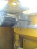
That is what i was thinking also about how the motor was still working . I took it apart today and pins 4 and 5 go to a little circuit board first then go to the motor . So i would think its a diode or something on the board that is bad . I and going to have to remove it all the way to get a better look at the board though. Once again thanks for your help.
If you have photos of the governor motor and its circuit please post some here.
No I did not, I found that in the manual the other day and started there. Also I can take a pic later today.How ever, did you check the voltage readings between the controller out put two wires for the governor mortor as i mentioned earlier, specially at the manual mode or when these two wires are open circuit ?
Because i asked it, as "Nige" sir said above it says resistance of motor should be" at least 1.5 ohms." But we excactly do not know that what should be the max reading.
If we can check the above voltage readings whether is it present, as i said at the manual mode then we can eliminate the controller from this issue.
If we can check the above voltage readings whether is it present, as i said at the manual mode then we can eliminate the controller from this issue.
Because i asked it, as "Nige" sir said above it says resistance of motor should be" at least 1.5 ohms." But we excactly do not know that what should be the max reading.
If we can check the above voltage readings whether is it present, as i said at the manual mode then we can eliminate the controller from this issue.
Ok update I went and read the error codes . I have an e15 Which says govern switch is in man or motor circuit is open and I have a e16 which mean proportional reducing valve circuit is shorted to body ground. I read voltage 739 and 740 in the in the manual position and had 0vBecause i asked it, as "Nige" sir said above it says resistance of motor should be" at least 1.5 ohms." But we excactly do not know that what should be the max reading.
If we can check the above voltage readings whether is it present, as i said at the manual mode then we can eliminate the controller from this issue.