• Thank you for visiting HeavyEquipmentForums.com! Our objective is to provide industry professionals a place to gather to exchange questions, answers and ideas. We welcome you to register using the "Register" icon at the top of the page. We'd appreciate any help you can offer in spreading the word of our new site. The more members that join, the bigger resource for all to enjoy. Thank you!

Boom down randomly becomes weak when warmed up - John Deere 490e excavator

joelx777

Well-Known Member
Joined
Apr 1, 2022
Messages
167
Location
Washington State
I am shooting in the dark here but appears you are talking about the "pump speed sensor" Maybe that is all the same? Certainly not on my CAT, but.....

Anyway, that diagram SUCKS! Hard to look at but appears that sensor is discrete (wires connect to nothing else), and only has 2 wires? If that is correct, that is likely an inductive pickup coil, in which it returns small voltage sine pulses back. Can confirm if there is a resistance spec for that sensor. If that is the case, you can easily just pull that plug from the ECM, put meter on it, and crank, ,and will be looking for AC BUT you have to be really careful as some RMS meters want to ignore anything outside of 60hz and this will be. A scope is your friend here!

If there is no AC wave form, go right back to the sensor. If you find it there, you have a culprit.

The AC amount is not that important. ECM will probably recognize anything over 5-10VAC, and will be looking for a sine wave so will have a trigger set in the programming. If it never hits that voltage, it is ignored.
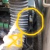
This is the engine speed sensor. The controllers use it to set idle, low, economy, and max power settings as well as to handle the auto idle circuit (when no functions are in use it returns the engine from the current settings to idle and waits for operator input to rev up again). I tested the engine speed sensor and it works great, I had a previous post on it. Now my problem is where these wires go and why I have what appears to be a short circuit between the two, maybe at the connector as you previously mentioned. I actually made several posts above, did you see them?

Your idea of pulling the connector from the engine controller is interesting... The manual says in a few dozen places not to try to run the machine though without it as it could cause permanent damage? This is one of the first machines they used a computer controller like this... It's a 1996 model year. The engine speed sensor does have just two wires and does have a resistance spec. Right now I just have a multimeter and toner / probe, sounds like I might need a different tool to check? As I mentioned before, the sensor tests out and works.

I cut the two prong connector off the engine sensor side so I could test the wires better. I have to fix that. I think there is a short circuit maybe in the controller side connector or maybe in the wiring. Not really sure where to go on it... The new wiring schematic I posted for the engine controller connector that says the two wires outlet on pins 4 and 11 does not match my actual testing of the connector.
 

fastline

Senior Member
Joined
Aug 8, 2011
Messages
1,110
Location
OK
If book states not to attempt cranking without plug, I would just go with that for now.

Look up an inductive pickup to understand their function to help you in diagnostics. They are self exciting, meaning they make a voltage when a piece of iron passes by them. I they are shorted, they will not die, but will not create a voltage the ECM can see. Yeah, that may be an issue.

Since the wire numbers do not align from actual and book, are you really certain you are checking the right pins in the plug? Be certain.

Your DMM should be able to see the resistance of a pickup, no problem. They are usually 100-1500ohms or so.
 

joelx777

Well-Known Member
Joined
Apr 1, 2022
Messages
167
Location
Washington State
I went out and worked on the excavator a bit this morning. I realized last night I had been testing the wiring harness connector backwards... I should have been testing from the right rear compartment with the engine sensor and testing for continuity from those two wires. When I did that this morning, I had continuity, meaning it was showing what it should be showing.

I want to be sure that the fault code 13 engine sensor is not just being caused by me turning the battery disconnect off. I put everything back together and then reset the computer codes. I very briefly ran the machine for maybe 2 minutes using various functions. When I turned it off the only code I still had was number 31. I have not yet replaced the boom up pilot sensor, so I know that code will return eventually. Maybe the engine sensor code number 13 will return too.

I am going to order the new boom up pilot sensor this morning. We are going on vacation till sunday, then I get back I'm going to operate it for a longer period and see what codes return and report back here.
 

joelx777

Well-Known Member
Joined
Apr 1, 2022
Messages
167
Location
Washington State
Well, here's my sad story:

I replaced the boom up pilot pressure sensor. I am still getting error 34, saying it's disconnected. The connector won't click when I try and push it together. Maybe I can find a replacement connector for it...

I had ordered the computer (palm pilot plus software). The eBay seller claims it was delivered, but did not actually deliver it. The post office says there was a different address on the package and the package only weighed 1 oz so it could not have been it. Sounds like I might have been scammed. Ugh.

I ran the machine for a while tonight after resetting the error codes and here's what I have:
30,31,32,34, 13,18.
 

fastline

Senior Member
Joined
Aug 8, 2011
Messages
1,110
Location
OK
You could try to chase one issue at a time, which I might suggest code 34. You did what most do which is replace the part when you get a code. I think you now realize it is not the sensor but the wiring or something else. I suggest old school testing with meters and possibly even a test light if you like those. They add load to the wire which can help troubleshoot.

But as I mention on the plugs, they get people! You can actually remove the pins from the connectors and adjust them and put them back if you are careful and have a clue. or get creative and put jumpers on all of that to confirm contact and see what you get.

As for ebay, send them a link for a palm pilot with the weight along with the USPS data. You should have enough to get a refund. Accept nothing less! They already know the guy is a scammer. They foster them on egay.....
 

joelx777

Well-Known Member
Joined
Apr 1, 2022
Messages
167
Location
Washington State
You could try to chase one issue at a time, which I might suggest code 34. You did what most do which is replace the part when you get a code. I think you now realize it is not the sensor but the wiring or something else. I suggest old school testing with meters and possibly even a test light if you like those. They add load to the wire which can help troubleshoot.

But as I mention on the plugs, they get people! You can actually remove the pins from the connectors and adjust them and put them back if you are careful and have a clue. or get creative and put jumpers on all of that to confirm contact and see what you get.

As for ebay, send them a link for a palm pilot with the weight along with the USPS data. You should have enough to get a refund. Accept nothing less! They already know the guy is a scammer. They foster them on egay.....
Thank you for your response! I like the idea of moving one issue at a time. I will keep working on 34 until it's fixed.

Any idea of where I could find a replacement connector to buy that matches it? Here is a picture https://photos.app.goo.gl/WqX5HJ7WCiRDqv8U9

I had tested the old boom up pilot pressure sensor with my multimeter and it looked dead. I hope to not just be a replace the part and hope it works guy! Though that might be a step up for me in terms of capabilities... ;)

I am wondering if there is just some gunk in the old connector preventing it from clicking in with the new sensor? The new sensor could also be an issue since Pape Machineries parts guy and the service guy were not completely sure this was the correct sensor... I'll check that too more closely.
 

fastline

Senior Member
Joined
Aug 8, 2011
Messages
1,110
Location
OK
Get better pics and send to Molex. They might help you. There are other resources online but I can tell you finding housings is a nightmare!

This is why I try to fix when I can. the white part is the housing, then the OEM buys the pins that they want. They all lock into the housings with some type of tab or tang. I have special tools to remove those pins and sockets! They are not expensive! $5! Or if you have good eyes, good light, and tiny tools, you can absolutely get them out without the tools. I do it all the time.

I recommend careful documentation, pics, then remove the pins and see how they all fit. they should be obviously tight, but if sloppy, you have a problem.
 

joelx777

Well-Known Member
Joined
Apr 1, 2022
Messages
167
Location
Washington State
Get better pics and send to Molex. They might help you. There are other resources online but I can tell you finding housings is a nightmare!

This is why I try to fix when I can. the white part is the housing, then the OEM buys the pins that they want. They all lock into the housings with some type of tab or tang. I have special tools to remove those pins and sockets! They are not expensive! $5! Or if you have good eyes, good light, and tiny tools, you can absolutely get them out without the tools. I do it all the time.

I recommend careful documentation, pics, then remove the pins and see how they all fit. they should be obviously tight, but if sloppy, you have a problem.
I purchased some tiny tools last night. I came out and cleaned off the connectors and plug for the boom up pilot pressure sensor this morning. I reset the codes and am currently only seeing 31. I am going to work it for a bit then see what codes are showing.
 

joelx777

Well-Known Member
Joined
Apr 1, 2022
Messages
167
Location
Washington State
Okay, this is strange. I ran the machine for about an hour and a half after resetting the codes this morning. I still only am showing code 31.

New theory: I added a battery disconnect switch on the batteries maybe a year ago due to a parasitic draw somewhere. I saw somewhere in the manual that disconnecting the batteries can sometimes cause a code to appear? It does seem like I have a lot of codes though... The machine generally runs well other than the weakness on boom down though.
 

joeheqmt

Member
Joined
Sep 17, 2023
Messages
19
Location
Ontario Canada
I went out and worked on the excavator a bit this morning. I realized last night I had been testing the wiring harness connector backwards... I should have been testing from the right rear compartment with the engine sensor and testing for continuity from those two wires. When I did that this morning, I had continuity, meaning it was showing what it should be showing.

I want to be sure that the fault code 13 engine sensor is not just being caused by me turning the battery disconnect off. I put everything back together and then reset the computer codes. I very briefly ran the machine for maybe 2 minutes using various functions. When I turned it off the only code I still had was number 31. I have not yet replaced the boom up pilot sensor, so I know that code will return eventually. Maybe the engine sensor code number 13 will return too.

I am going to order the new boom up pilot sensor this morning. We are going on vacation till sunday, then I get back I'm going to operate it for a longer period and see what codes return and report back here.
Hello Joelx I also have a 490E and I was wondering if you could help me out the alternator resistor located behind the seat on the left hand side of the cab (when sitting in the seat) 2 wire device bolted to the left of the relays red/white and blue/yellow.
Mine is blown and I cannot read or measure the resistance
If you could help me out and read or measure how many ohms it is I would greatly appreciate it thank you
 

joelx777

Well-Known Member
Joined
Apr 1, 2022
Messages
167
Location
Washington State
Hello Joelx I also have a 490E and I was wondering if you could help me out the alternator resistor located behind the seat on the left hand side of the cab (when sitting in the seat) 2 wire device bolted to the left of the relays red/white and blue/yellow.
Mine is blown and I cannot read or measure the resistance
If you could help me out and read or measure how many ohms it is I would greatly appreciate it thank you
Happy to help! I am not near my machine now, but here is the manual says it is 40 amps, see below. Can you send me a video of picture of what you are talking about so I can find it in person for you?
Screenshot_20230917-185336.png
 

joelx777

Well-Known Member
Joined
Apr 1, 2022
Messages
167
Location
Washington State
Hello Joelx I also have a 490E and I was wondering if you could help me out the alternator resistor located behind the seat on the left hand side of the cab (when sitting in the seat) 2 wire device bolted to the left of the relays red/white and blue/yellow.
Mine is blown and I cannot read or measure the resistance
If you could help me out and read or measure how many ohms it is I would greatly appreciate it thank you
Also- here is what the wiring diagram shows... it doesn't give a resistance though. If you send me a picture in your machine of where you want me to test resistance, I'll do it in mine.
1000004558.png
 

fastline

Senior Member
Joined
Aug 8, 2011
Messages
1,110
Location
OK
Hello Joelx I also have a 490E and I was wondering if you could help me out the alternator resistor located behind the seat on the left hand side of the cab (when sitting in the seat) 2 wire device bolted to the left of the relays red/white and blue/yellow.
Mine is blown and I cannot read or measure the resistance
If you could help me out and read or measure how many ohms it is I would greatly appreciate it thank you
I don't know your hoe but I do commonly work with the Delco alternators and suspect yours is a 10SI 3 wire. The resistor you see is technically not needed IF you wire the warning light correctly. A light bulb works as a series resistor and basically that they are using it for is current limiting.

You will notice on the diagram that D is continued with the D (warning light). I'm sure Deere probably put both on just for people that hack wiring, but if you go through your small dash warning light in series, you will be fine. That light should go to ground (light turns off) when alt is working correctly.
 

joeheqmt

Member
Joined
Sep 17, 2023
Messages
19
Location
Ontario Canada
Hi fastline thanks for the reply
My alternator is a Bosch and has 2 wires the output and the field terminal with an internal voltage regulator. 24 V unit
I don't know the model of the top of my head but I could remove it from the machine and find out

Yes you are right the resistor is a current limiting it also drops the voltage to about 5 volts for the monitor controller CPU
Do you happen to know what current the field winding typically takes.
I'm not sure how to wire it through the warning bulb as you suggest. Not clear on your idea but it sounds interesting
Thanks again
 

joeheqmt

Member
Joined
Sep 17, 2023
Messages
19
Location
Ontario Canada
Happy to help! I am not near my machine now, but here is the manual says it is 40 amps, see below. Can you send me a video of picture of what you are talking about so I can find it in person for you?
View attachment 294720
Hi Joe lx.

the resistor is mounted to the side of the relay holder its behind the seat behind the air and cable duct at the door side of the cab
I have taken a picture but I have to figure out how to attach it
 

Attachments

  • 20230918_163938.jpg
    20230918_163938.jpg
    2 MB · Views: 5

fastline

Senior Member
Joined
Aug 8, 2011
Messages
1,110
Location
OK
Using a resistor to drop voltage is not a reliable method without both knowing and maintaining a constant current. V=IR. I am not sure why they would do that but I have seen series resistors just to drop V a bit before a real regulator tames the voltage.

Just as the poor boy method of running an LED with a resistor, if the input voltage goes up, so does the output, then the current! poof!

Are there no numbers on the resistor? Many are actually coded.

If you are running a Bosch, I recommend you figure out the model and look up their wiring to understand it. I don't want to feed you bad advise.
 

joeheqmt

Member
Joined
Sep 17, 2023
Messages
19
Location
Ontario Canada
This is the resistor removed it is mounted with a round head philips machine bolt door side by the safety lock lever wires red white and blue yellow still attached
 

Attachments

  • 20230918_164306.jpg
    20230918_164306.jpg
    2.9 MB · Views: 6

joeheqmt

Member
Joined
Sep 17, 2023
Messages
19
Location
Ontario Canada
Using a resistor to drop voltage is not a reliable method without both knowing and maintaining a constant current. V=IR. I am not sure why they would do that but I have seen series resistors just to drop V a bit before a real regulator tames the voltage.

Just as the poor boy method of running an LED with a resistor, if the input voltage goes up, so does the output, then the current! poof!

Are there no numbers on the resistor? Many are actually coded.

If you are running a Bosch, I recommend you figure out the model and look up their wiring to understand it. I don't want to feed you bad advise.
No nothing legible its a ceramic wire wound 10 watt that's all I know
 

joeheqmt

Member
Joined
Sep 17, 2023
Messages
19
Location
Ontario Canada
The picture below shows the wires to the resistor still attached the connectors can be pulled apart to measure the resistance. The red white wire carries the power 24 v but it is dead with the key in the off position the blue yellow goes to the field terminal of the alternator and to the CPU monitor controller
Let me know if you require more information
Thanks
 

Attachments

  • 20230918_164737.jpg
    20230918_164737.jpg
    3 MB · Views: 5
Top