• Thank you for visiting HeavyEquipmentForums.com! Our objective is to provide industry professionals a place to gather to exchange questions, answers and ideas. We welcome you to register using the "Register" icon at the top of the page. We'd appreciate any help you can offer in spreading the word of our new site. The more members that join, the bigger resource for all to enjoy. Thank you!

580C Cutout Solenoid Repair

RDC_580C

Well-Known Member
Joined
Apr 3, 2017
Messages
109
Location
VA
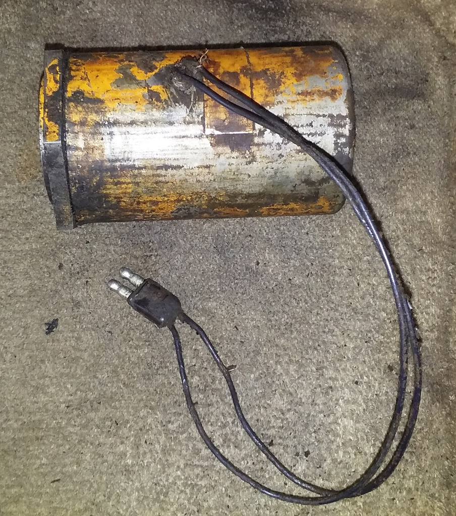
Thought I'd post my repair of the Cutout Solenoid, since I couldn't find any internal pics floating around online.

COS_Removed.jpg


COS_Wire_Damage.jpg


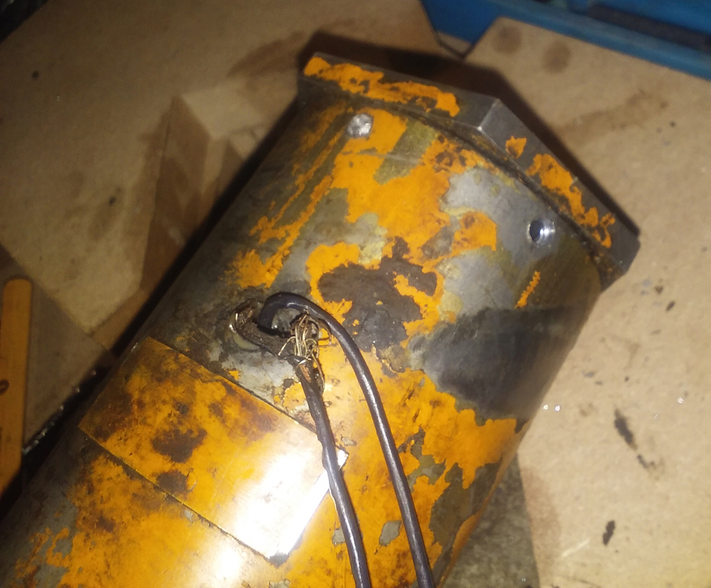
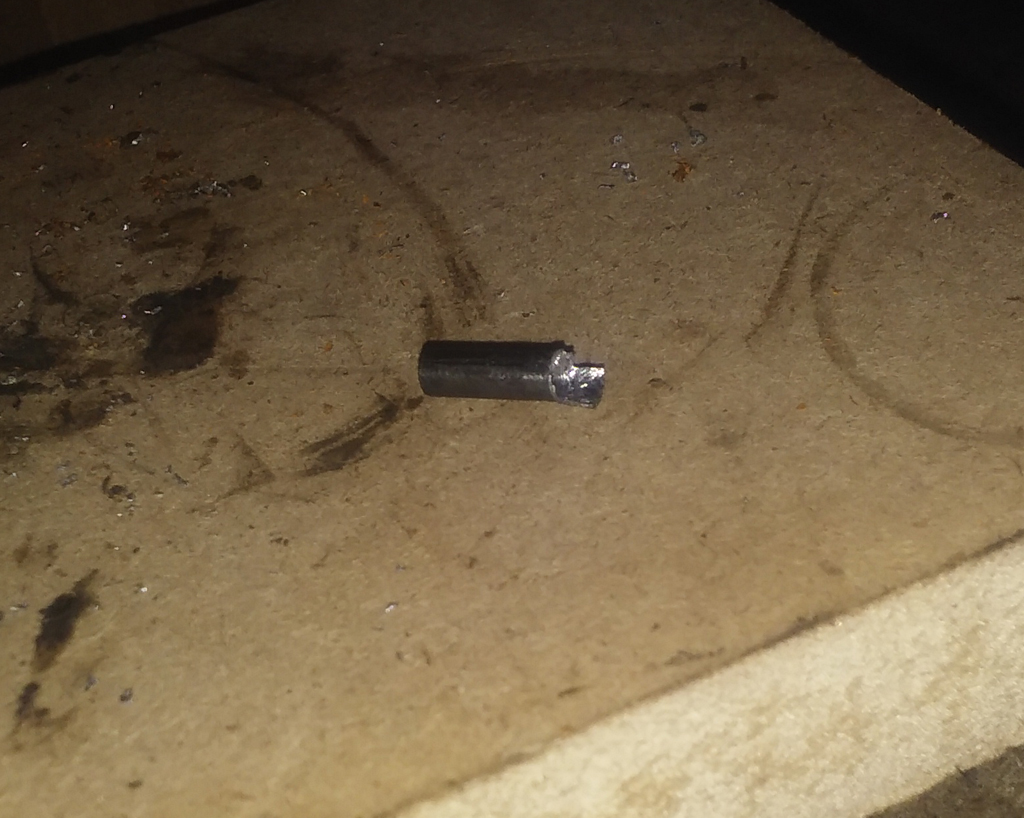
The 6 pins that hold the cap on pretty much just fell out after the 'heads' of them were drilled.
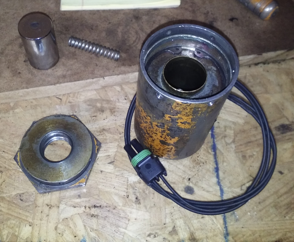
COS_Pins.jpg


Cap removed.

COS_Cap.jpg


Plunger and Spring removed.

COS_Cap_Removed.jpg


Plunger, Spring, Cap and drilled out Pins.

COS_Plunger.jpg


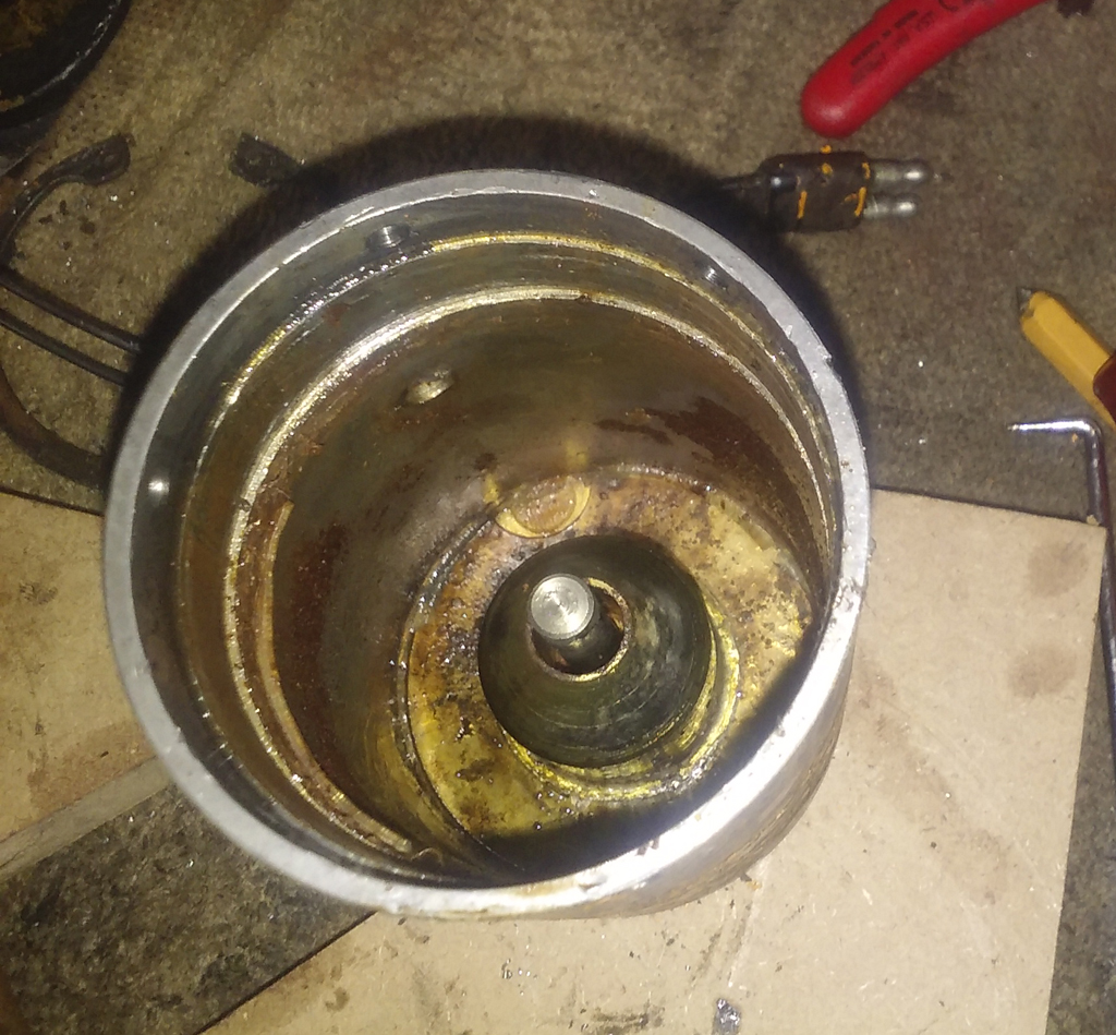
Under the silicone is an internal snap ring that needs removed so the coil can come out.

COS_Snap_Ring.jpg


Coil removed.

COS_Tube.jpg


Coil.

COS_Coil_Removed.jpg


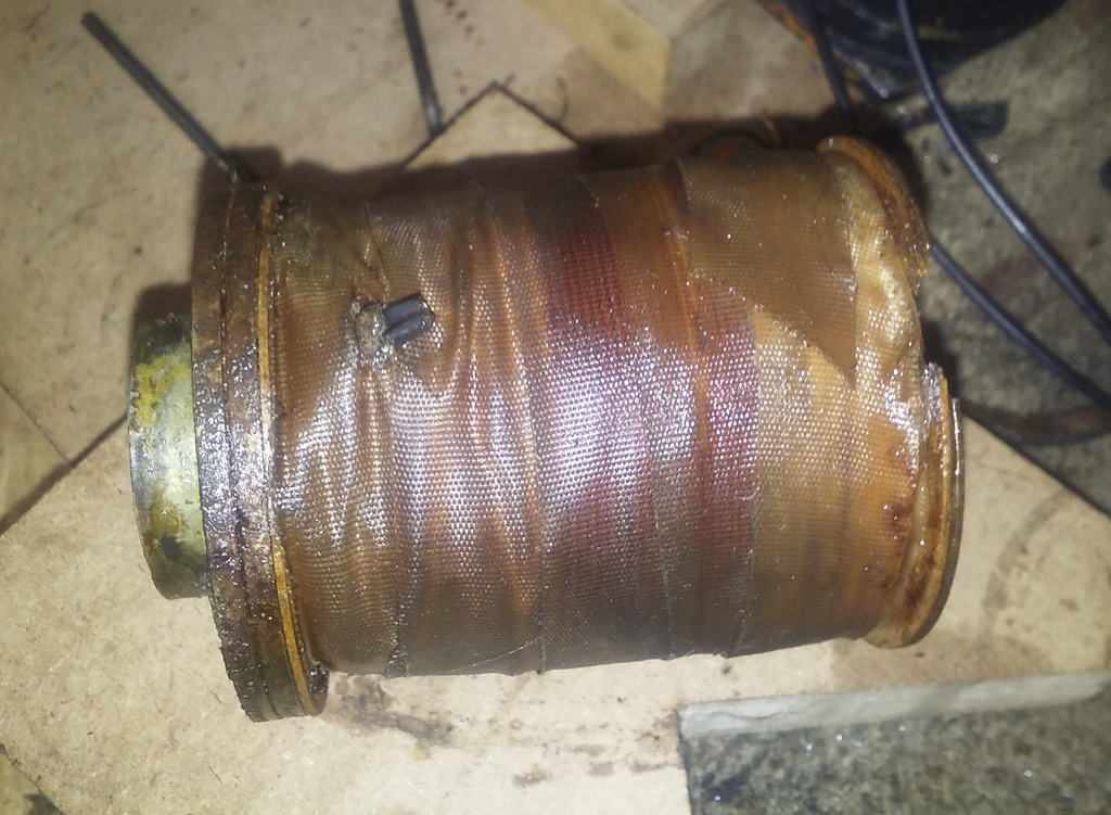
Tape removed from coil.

COS_Tape_Removed.jpg


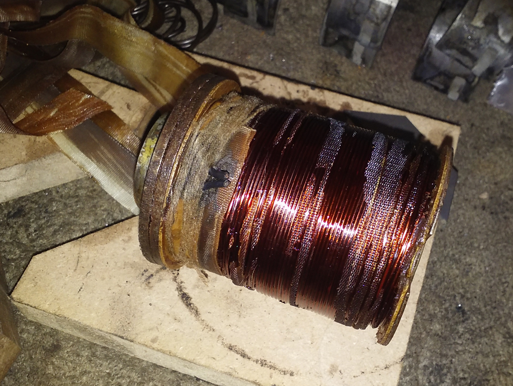
String removed from coil. This holds the wires in place against the coil and keeps it from unwinding.

COS_String_Removed.jpg


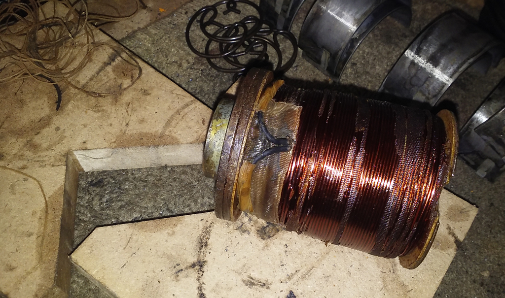
Just a couple more pieces of insulation to expose the Solder joints.

COS_Wire_Solder.jpg


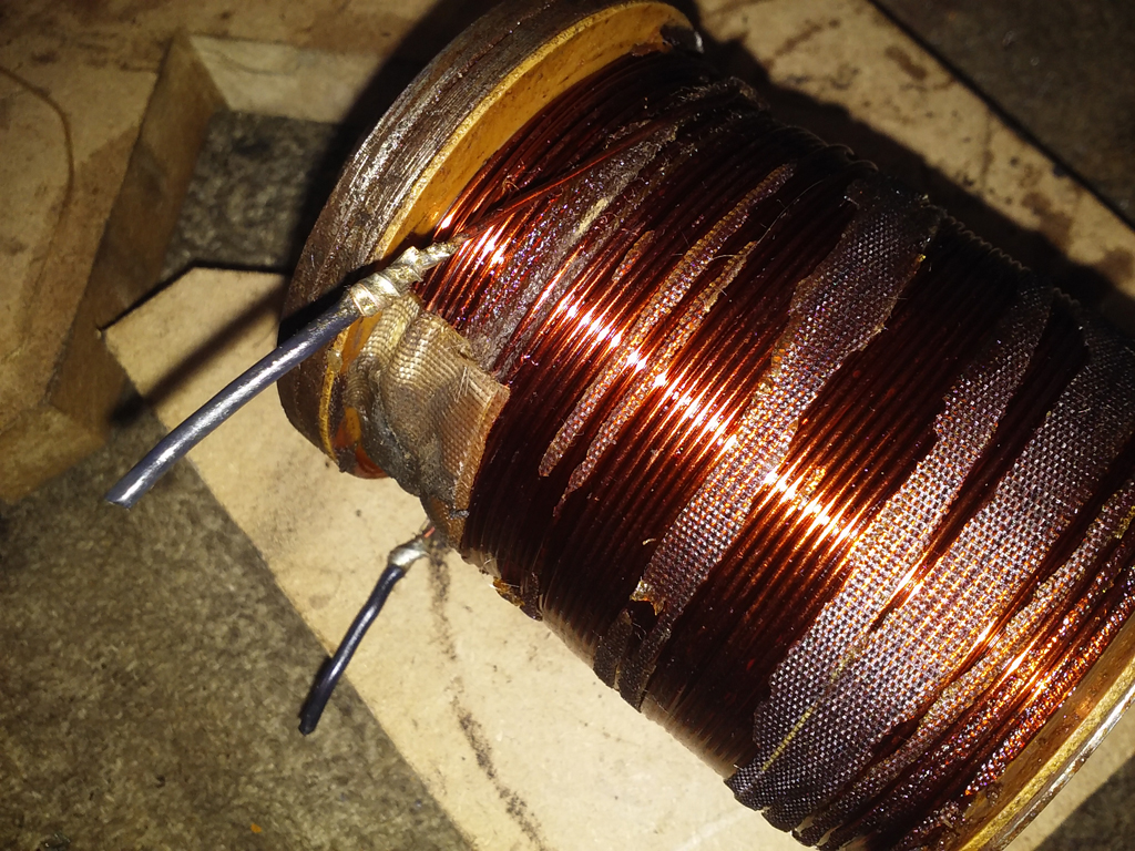
At this point I took the coil home to put it on the bench and do some tests, mainly for my own curiosity, but also for the sake of documenting it and for anyone else that might be interested...

This one measures right around 2.8ohms and draws around 4.3A at 12v

The wires are 16awg stranded, that's the wires from the connector to the coil.

The coil is wound from 20awg magnet wire, and if the math is right, there is around 275ft of it on there, so if you have to rewind one, enjoy. ;)

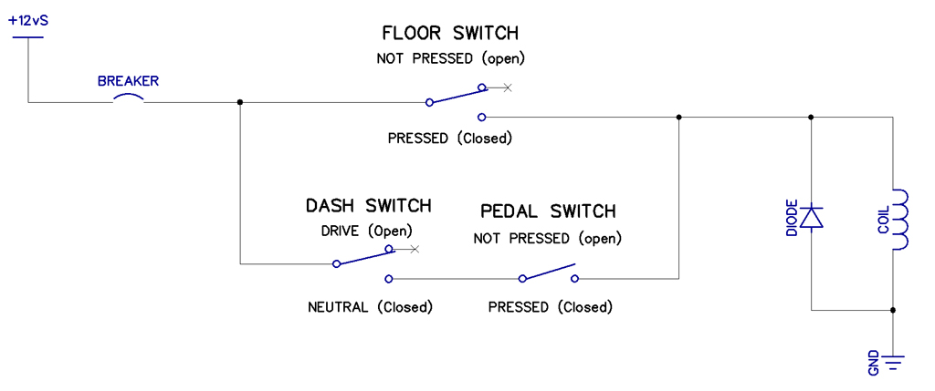
It's not polarized (does not have a + and - side) so it can be wired up either way and still work, also why the connector is not keyed.

Sorry, didn't get any pics of the rewire, restring and retape of the coil, but it's all pretty much the reverse of the above, just nicer looking now. I've also redone the connector with a 2 pin Weatherpack, as the entire tractor is getting a rewire.
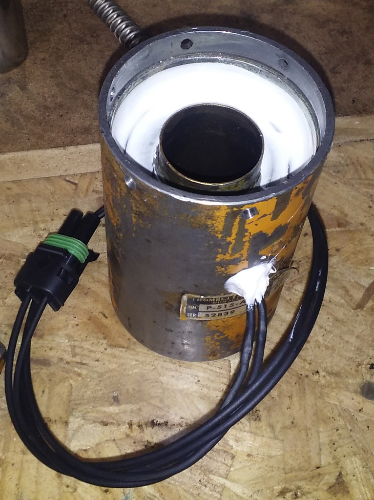
Coil reinstalled.

COS_Coil_Installed.jpg


New Silicone.

COS_388.jpg


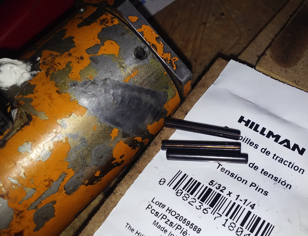
Just decided on tension pins (length cut to fit) to hold it all back together for now, as this wasn't intended to be a full restoration or anything, just getting the old gal working complete again for now.

COS_Tension_Pins.jpg
 
Last edited:

RDC_580C

Well-Known Member
Joined
Apr 3, 2017
Messages
109
Location
VA
@ Andy01 - It was just the wire that was chewed up and needed replacing. It's a pretty robust solenoid, so one that had any other issues with the solenoid itself would probably be pretty rare, or have to be from some obvious abuse. The rest of the Cutout circuit in the 580C that powers it is fairly simple. A Breaker, Toggle switch (dash), Roller type limit switch (floor) and another Limit switch on the Brake/Clutch pedal (next to throttle pedal) that can power the Solenoid. Then the protection Diode (very important) to clamp the voltage spike when the coil is turned off, as this can be hundreds of volts.

The floor switch circuit is 12vS (12v after the main Solenoid) to Breaker, Breaker to floor switch (Common) then floor switch (NO, Normally Open) to the Solenoid. So when that floor switch is pressed the circuit is closed and the Solenoid will get 12v. It works regardless of how the Neutral/Drive Dash switch is set.

The Dash and Brake/Clutch switch circuit is 12vS to Breaker (same Breaker), Breaker to Dash switch, Dash switch to Pedal switch, Pedal switch to Solenoid. With the Dash switch in the Neutral position it is Closed, and it will allow the Pedal switch to make the Solenoid activate. In the Drive position the switch is Open and the Pedal switch will do nothing. It's kind of a half safety half feature thing so if you were to press that Brake/Clutch pedal while going down a hill the Solenoid will not engage and put you basically in neutral, where gravity would quickly take over and things could get nasty. So if everything is wired up correctly, Drive is the position to leave the switch in if roading the machine or on any kind of hills, Neutral is for flat ground where you're doing FEL work in a pile or loading onto a truck, so when you press that pedal to stop the Shuttle can cutout and it's no longer a drag on the engine while you run the hydraulics.

Here is a more updated schematic of just the Cutout Solenoid section and it's related components, probably makes more sense than the babble up there.

COS_Schematic.jpg


@ Tinkerer - I wouldn't call much on this old girl electronic ;) but that's what I do love about her, simple. I'm more of the 'if it's broken I'll look at it' type, as I'm always interested in learning something new or trying to fix what others might consider useless, pointless or not even worth it, but electronics are something I've been a bit more into over all of the years so far.


@franklin2 - Correct, this is the Clutch Cutout Solenoid on the side of the Shuttle.
 
Last edited:

xgiovannix12

Senior Member
Joined
Feb 22, 2012
Messages
474
Location
New York
Occupation
Operator/Mechanic/Truck driver
do you know the color of the wire for the brake switch? Mine does not work i just never traced it down
 

RDC_580C

Well-Known Member
Joined
Apr 3, 2017
Messages
109
Location
VA
The short answer to that is Tan for the Left and Right Brake Pedal switches. For the Brake/Clutch switch they are Light Blue.

The more detailed one I'd have to start a new thread about as that Brake light circuit is also the Turn Signal light circuit and that wire color does not stay Tan for the entire run, nor is it the same for a cab versus canopy and even the wiring diagram shows they may have used a couple of different colors for this or that in there.

Add on top of that it's 4 decades old and who knows who did what in there over the years and it could be a real mess. One of my Brake switches was inside the cab in the toolbox, and none of the wiring was under there for any of it, so I've just opted to redo the entire thing and get it back up to snuff, as well as make up a new wiring diagram/schematic of what all goes where. The original wiring diagram isn't too bad, but it does leave some to be desired.
 

franklin2

Senior Member
Joined
Aug 6, 2016
Messages
309
Location
Virginia
Have you used this system yet? Mine on the 480c didn't work either. It turned out to be the dash switch was broken, and the switch on the brake pedal needed to be cleaned up. My floorboard switch was frozen but I took it out of the circuit temporarily.

After all that, and some more wiring at the main relay to the ignition switch, I got it working and so far, I hate it. I may need to adjust the pedal switch some, but right now I have it disengaging the shuttle, and then applying the brake.

If you are on a hill, put the lever in forward and slowly let off the brake it drifts backwards and scares you a little bit. So you either press on the brake again or tell yourself to go ahead and let off the brake and then the shuttle suddenly engages and the whole tractor lurches forward and can pull a wheelie depending on how steep the slope is.

When you are going down a hill and want to touch the brake a little bit to control your speed, the shuttle will disengage and the tractor will suddenly be going faster instead of slowing down.

I thought I would like it, if you have the engine rpms up and the trans in 1st gear, you need two feet on the brake pedal to get it to stop. And sometimes my brakes lock up and won't release, I thought holding the tractor back with the brakes was aggravating that problem.

I have found for maneuvering from place to place, it's best to keep the idle down and when you need to go, just use the "gas pedal" on the right floorboard to get the rpms up.

Anyone have this setup and it is adjusted like it's supposed to be? I have quit using mine.
 

RDC_580C

Well-Known Member
Joined
Apr 3, 2017
Messages
109
Location
VA
If you have it wired up correctly, then it just sounds like you need to flip the Drive/Neutral switch is all.

That's what the Drive/Neutral switch does when it's in Neutral. In Drive, when you press the Brake/Clutch pedal (the one right next to the Throttle Pedal) the Cutout will NOT engage and the Shuttle stays connected, so there is no free rolling like it is doing to you there. Sounds like you have it in Neutral, where when you press the Bake/Clutch Pedal the Cutout DOES engage and you are effectively in Neutral, that's normal, but it for sure is no es bueno on the hillys or when you're on the road, that needs to be set to Drive then so the Cutout Solenoid will not work when the Brake/Clutch Pedal is pressed.

The Floor switch on the Left will always make the Cutout work, doesn't matter what the Dash switch is set at. That one is mainly for changing gears while driving.
 

franklin2

Senior Member
Joined
Aug 6, 2016
Messages
309
Location
Virginia
So what would you use the cut-out for then? Mine does work, when I said "I don't use mine anymore" I mean I leave the switch in drive all the time. Going to neutral to change gears on the fly makes sense, I am wondering what else you would use this feature for? I am tempted to see if I can adjust the pedal switch to disengage when the brakes are already being applied with some moderate pressure.
 

RDC_580C

Well-Known Member
Joined
Apr 3, 2017
Messages
109
Location
VA
It's used for when you need to brake and can get that little extra bit of power into the hydraulics, for loading/lifting something a bit heavier up higher, and has already been mentioned it's not for when you're on any kind of hill at all, as that's just asking for an accident. Since right into Neutral it goes, the brakes need to be in good form to handle all of the slowing/stopping then, and unless they have just been redone most of them aren't really up to that task.
 

xgiovannix12

Senior Member
Joined
Feb 22, 2012
Messages
474
Location
New York
Occupation
Operator/Mechanic/Truck driver
even good working brakes wont handle the machine on a good hill. I normally downshift to a lower gear when coming to a hill. My clutch works but never worked with the brake pedal and I like it that way
 

RDC_580C

Well-Known Member
Joined
Apr 3, 2017
Messages
109
Location
VA
Hey xgiovannix12, I sent you a message about the brake switch wiring, not sure if that's what you were wondering about or if it was the brake/clutch wiring.
 

xgiovannix12

Senior Member
Joined
Feb 22, 2012
Messages
474
Location
New York
Occupation
Operator/Mechanic/Truck driver
Hey xgiovannix12, I sent you a message about the brake switch wiring, not sure if that's what you were wondering about or if it was the brake/clutch wiring.

yes I seen it . then I thought about it engaging when me going down the road so I figured to let it be. it works but not with the brakes. I might wire up a switch on the loader handle like the 580se had
 

Geno462

New Member
Joined
Dec 15, 2017
Messages
1
Location
Shenandoah
Just wanted to say Thanks. I wrote this option off being an older machine, but with your pics and direction I pulled it off. Thanks Geno
 

RDC_580C

Well-Known Member
Joined
Apr 3, 2017
Messages
109
Location
VA
Amazon has it too, for a measly $565 and then $1.99 shipping. :eek:

Wonder what they charge for it? Anything more than a bill is just insane for that solenoid, and at almost 6 bills I'd think you should fill out a police report for being robbed. I'd rewind the thing by hand, not using a drill, by hand, before I coughed that up for one.
 

rogue7573

New Member
Joined
Aug 6, 2015
Messages
2
Location
southwest va
Very nice explanation of how this system works. I was curious about what it does and on my 580c the switch (dash) really does nothing so I figured there was a issue with it. Hills scare me enough with this thing and I couldn't imagine going down a steep hill and have it go into neutral. I believe ill just leave it the way it is on my machine.
 

RDC_580C

Well-Known Member
Joined
Apr 3, 2017
Messages
109
Location
VA
Thanks. I installed a toggle switch with a red cover on it for that thing, so it's just a little more eye catching and can't be flipped accidentally, and then when I want to use it there's that little extra step of having to flip the cover up to be able to flip the switch.
 
Top