skyking1
Senior Member
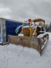
yup it's an old 6 and not a production or finish machine.
I get your perspective, don't let perfect be the enemy of good.
I get your perspective, don't let perfect be the enemy of good.

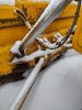
A 1000 hours would be more than I'll ever see turn up on the clock, I like the grease idea too.Make yourself a template of the rear lower least worn side of the ball to aid in the buildup and final grinding-to-shape after the build-up. Also, during final assembly add some grease between the trunnion ball and the c-frame to help the initial wear-in. If done accurately it should last at least 1000hrs in your application
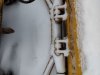
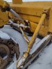
I'm pretty thickheaded Nige, I guess I don't know what you are calling the yoke..are taking about something on the back side of the blade? or the trunnion ball area?Take a close look at the half of the "yoke" that is welded to the push arm assembly - left side of your 2nd photo. Can you find a casting number on it, or anything on the cap side for that matter.?
The piece that goes around the trunnion ball is called a bearing and cap; the bearing being welded on the push arm.I think you are calling the yoke the clamp that wraps around the trunnion ball correct?

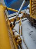
I see the plates can be removed and spacers added to take up space without a lot of effort, that's the next place I was going to focus on after I get the trunnion area tightened a bit.I believe I could even make what ever spacer plates I will need. ThanksYou don't have to do anything at the trunnion ends of the push beams. Side to side play is at the blade attachment points. The sway is in the K braces and the beam to blade attachment points. Clean the snow off the top of the K brace and you will see where plates are installed to take up the slop in the ball and socket joints.