• Thank you for visiting HeavyEquipmentForums.com! Our objective is to provide industry professionals a place to gather to exchange questions, answers and ideas. We welcome you to register using the "Register" icon at the top of the page. We'd appreciate any help you can offer in spreading the word of our new site. The more members that join, the bigger resource for all to enjoy. Thank you!

TMZ-34 Outriggers inop

SanMarcosMike

Member
Joined
Aug 2, 2023
Messages
10
Location
San Marcos, Texas
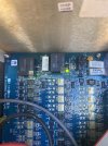
I have a 2003 TMZ-34 trailer mounted lift. After last use the outriggers would not retract. The boom functions normally and there are no fault codes displayed. There was some damage on outrigger wiring so a new outrigger wiring harness was installed. I’ve tested the limit switches on the boom (4) and they are good so the unit knows the boom is stowed. I’ve checked the switches on the outrigger pads and they are correct. I’ve tested the coils on the outrigger cylinders per the service manual and they are good. I’ve tested the coils on the outrigger manifold and they’re good as well. This unit has blue circuit boards and automatic hydraulic leveling. Overlay decal type buttons on the control box. Inside the ground control box the connection board on the back has two green LED lights. One labeled E Shutoff OK is illuminated. The other labeled Outriggers OK is NOT illuminated. I find no reference to this Outriggers OK light in the service manual. The light not being on indicates a problem. But what problem? There is no response when the buttons are pressed to move the outriggers and no power sent to the cylinder coils while buttons are depressed. Any suggestions will be greatly appreciated.
 

Mechanicsville804

Well-Known Member
Joined
Dec 14, 2021
Messages
116
Location
Virginia

Hi San Marcos Mike I hope this helps, this is a link to a previous thread that described a similar problem to yours.
 

SanMarcosMike

Member
Joined
Aug 2, 2023
Messages
10
Location
San Marcos, Texas
Still against a brick wall. Does no one know what causes the green outriggers okay light on the connector board to go out? It has to be there as an indicator. What problem it it pointing to? I find no reference to the light in the operators manual, the service manual, or the parts manual. Genie tech support will not assist anyone but their distributors. When you lookup their distributors they are all rental companies that don’t work on outside equipment.
3862BD84-4F91-483A-9129-5C8CCE8F2344.jpeg
 

Engineer44

Well-Known Member
Joined
Nov 30, 2017
Messages
60
Location
Portland
Hmm, did you make any headway on this? Sounds like you’ve tried the obvious stuff. There used to be issues with the membrane buttons. The machine would detect a button press if there was a bad membrane and the machine would go stupid. Did you try unplugging the platform control’s from the ground control box to see if that had any effect? I wouldn’t think an auto leveling issue would prevent retracting. If there was wiring damage you might have to carefully ring out all the conductors, including to the boom switches. If there were a wiring issue the machine may not know the booms are stowed even though the switches themselves checked OK. If you got it resolved let us know so we can learn. Good luck.
 

SanMarcosMike

Member
Joined
Aug 2, 2023
Messages
10
Location
San Marcos, Texas
No progress so far. Apparently the purpose of the Outrigger Okay light on the connector board is a state secret. I can’t find anyone who knows what causes that light to go out. The outriggers are not stowed. That’s the problem. I can’t retract them. All other functions on the boom work normally from the ground or the platform. No fault codes at all. Outrigger wiring harness is new as a result of this problem. Disconnecting the ribbon connector from the control overlay has no effect. I’m convinced that the key is the light being out on the connector board. Does it indicate that the board is bad? The light is not referenced in any of the manuals, including the service manual. Nothing on this thing is cheap, so I don’t want to just throw parts at it. Any help is appreciated.
 

Engineer44

Well-Known Member
Joined
Nov 30, 2017
Messages
60
Location
Portland
I’m just wondering if the control board is satisfied that the booms are stowed. Something to check very carefully are the big connectors that bring all the wiring to the back of the ground control box. I recall threads years ago on this machine about individual pins in a connector not fully seated and locked in the connector. When the connector was plugged into the ground control the loose pin would just push back into the connector and not make a reliable connection with its mate. Visual inspection of each pin and push on each pin with a piece of plastic or wood to make sure it’s locked. Just something relatively easy and no cost to eliminate. I do know that used to be an issue. If that’s not it we’ll keep thinking!
 

SanMarcosMike

Member
Joined
Aug 2, 2023
Messages
10
Location
San Marcos, Texas
I did see that post. The retaining ring on the amp connector was missing and it wasn’t seated. That’s not the case here. The outriggers are extended and I have a green light for each outrigger. If I manually move the level sensor, I get an alarm and the lights flash indicating that it’s not level. If I disconnect one of the pressure switches on the outrigger pads, the same response. So the unit knows the outriggers are down. I just get no response when I try to move them.
 

Engineer44

Well-Known Member
Joined
Nov 30, 2017
Messages
60
Location
Portland
It sounds like the outrigger switches and their wiring is OK. The control board knows they are all down. I’m not sure even if the system didn’t know they were down why that would prevent them from being raised. I wish Genie had provided schematics for the blue boards. (They do have schematics for the relay based upgrade system.)
I am wondering if the control board monitors the health of the solenoid coils and if it senses they are all OK you get a green light. I’m just going from memory but there would be two coils for each outrigger solenoid, one extend and one retract. All the wiring from those solenoids lands in one connector at the ground control box. It’s possible the control board checks continuity/resistance on those coils on power up and if one fails, no green light.
Again testing my memory, are there are individual buttons to raise each outrigger separately? If so I’m assuming they don’t respond either.
When you command the outriggers to retract can you hear the solenoids move? I’m assuming the pump doesn’t run and everything is quiet. Have you put a voltmeter on a retract coil to verify whether or not 24 volts gets there?
As long as that pesky blue board is OK you should be able to eventually run this down.
 

SanMarcosMike

Member
Joined
Aug 2, 2023
Messages
10
Location
San Marcos, Texas
I have tested the coils on each outrigger solenoid and the outrigger manifold per the service manual. All test good. I have also checked to see if voltage is being sent to the outriggers or the manifold when the buttons are pushed and no voltage is being sent. This unit does have individual outrigger buttons as well as the auto leveling function. The individual buttons do not function either. When the outriggers buttons are pressed there is no response and no sound because no power is sent to any of the solenoids. I appreciate the brain storming though, keep it coming.
 

Engineer44

Well-Known Member
Joined
Nov 30, 2017
Messages
60
Location
Portland
It’s a head scratcher. I’m no expert but I do own the same machine. Did you check the coils at the solenoid or from the ground control board? If you test right from the ground control board it would prove out the connector and the wiring to the coils as well as the coils themselves. Did the machine work correctly for a time after the outrigger harness was replaced? The drivers on the blue board that activate the solenoids wouldn’t all fail at once. You said the booms work normally so I’m assuming the batteries are good. If you had to move the machine you could run the pump and jumper the retract coils one at a time to raise them up.
 

SanMarcosMike

Member
Joined
Aug 2, 2023
Messages
10
Location
San Marcos, Texas
The outrigger harness was replaced when the outriggers would not retract after using the lift. So the problem existed prior to the new harness. The batteries are good. The coils were tested at the solenoids per the service manual. I have no idea how you would test the from the control board. You’re testing the resistance in the coil. There are not separate solenoids for extending and retracting the cylinders. When you press the buttons to activate the outriggers no voltage is sent to the outrigger manifold at the pump. The pump does not run for the outrigger functions at all. But it works normally for all boom functions.
 

Engineer44

Well-Known Member
Joined
Nov 30, 2017
Messages
60
Location
Portland
The wiring for all four outrigger switches and solenoid coils runs back to one big plug that connects to the CPU board. It’s labeled P3 on the CPU board. The pin numbers are shown on the electric schematic in the service manual. I would test the switches and coil resistance from there to rule out any wire or connection issues. If it were me I’d pull that plug and carefully inspect the pins to make sure they are all locked in place. If all tests OK then you’ve ruled that out and the issue is closer to the control panel.
 

Engineer44

Well-Known Member
Joined
Nov 30, 2017
Messages
60
Location
Portland
You could short pins 10 and 22 together on connector P3 to bypass all the boom switches and their wiring. Those switches are all in series and must all be closed to indicate the booms are stowed. I know you said you tested the individual switches but you can quickly bypass that whole circuit by connecting pins 10 and 22 briefly for testing purposes. That would prove out the wiring and connector as well as the switches. Similarly you could also short pins 24 and 25 together to bypass the negative boom angle switch if yours is equipped with that. As you already know, the outriggers won’t retract unless it’s satisfied the booms are stowed.
 

Mechanicsville804

Well-Known Member
Joined
Dec 14, 2021
Messages
116
Location
Virginia
The outrigger harness was replaced when the outriggers would not retract after using the lift. So the problem existed prior to the new harness. The batteries are good. The coils were tested at the solenoids per the service manual. I have no idea how you would test the from the control board. You’re testing the resistance in the coil. There are not separate solenoids for extending and retracting the cylinders. When you press the buttons to activate the outriggers no voltage is sent to the outrigger manifold at the pump. The pump does not run for the outrigger functions at all. But it works normally for all boom functions.
Have you tried to stow the outriggers manually and start over from the beginning to see if that will help?
 

SanMarcosMike

Member
Joined
Aug 2, 2023
Messages
10
Location
San Marcos, Texas
The outriggers are hydraulic and cannot be retracted manually. I moved the lift by disconnecting the cylinders and lifting the cylinders and outriggers and wiring them in place. Once positioned where I want to work on the lift I lowered the outriggers and reconnected the cylinders. As for the limit switches on the boom, I tested them individually. I just assumed if there was voltage present at the switch then the wiring must be good. I’m certainly willing to try to test the boom switches at the connector if I had some idea how to go about that. Forgive my ignorance but the pins are not numbered and there is no schematic showing pin placement. Also you would have to disconnect the cannon plug to get at the pins which would render the system inoperative anyway. If I disconnect the outrigger cannon plug from the connector board and turn on the key to power the system I get the following indications: The lights for the individual outriggers blink and the warning beep sounds, which indicates that the pressure switches on the feet are not reporting the feet on the ground and the beep warning that it’s not level and safe to use the boom. I also get alternating fault codes 01 and 02 . Fault 02 indicates no negative angle boom switch, which is the only boom switch run through the outrigger cannon plug. The fact that no fault codes are present when the cannon plug is connected indicates that the negative boom angle switch is working and reporting back to the board. Fault 01 is a little more mysterious. It is a safety circuit fault indicating the outriggers up with no retract structure switches. The machine would assume the outriggers are up because the pressure switches on the pads aren’t reporting them on the ground, fair enough. But if there are retract structure switches on this year model, I have been unable to locate them. In any event there are no faults with the cannon plug connected so that may be Irrelevant.
 

Engineer44

Well-Known Member
Joined
Nov 30, 2017
Messages
60
Location
Portland
My machine doesn’t have the fully retract sensor swiches either. Just the switches on the feet that close when the feet are fully down with weight on them.
The connector pin layout is labeled if you look close. 1-12 on row one, 13-24 on row two and 25-35 0n row three. I may be off a digit on row 2 and 3 but you get the idea.
Do you have the old harness? Wondering if any of the pairs to a solenoid were shorted. And if so does the circuit board have over current protection for the drivers that operate the solenoids. Hopefully the driver wouldn’t self destruct if it was connected to a short. I don’t know the answer to that.
I wish I had a breakout box with a male 35 pin and easy to access test points. That would speed testing.
 

SanMarcosMike

Member
Joined
Aug 2, 2023
Messages
10
Location
San Marcos, Texas
Now that you mention it, I think that I read somewhere in the service manual that all of the solenoids had a surge protection built into them to protect the board. There was a test procedure for that as well. If the old wiring harness looked shorted bad enough to replace, it may very well have toasted a solenoid surge protector which might not make the coil test bad. At least now I have a lead to run down. Thanks a lot for brainstorming this problem. I’ve been at it off and on for weeks and had about run out of ideas.
 

SanMarcosMike

Member
Joined
Aug 2, 2023
Messages
10
Location
San Marcos, Texas
Just found it in the service manual. There are spike suppression diodes built into the coils. Besides checking the coils for resistance (which I’ve done) there’s a procedure to check the spike suppression diode with a nine volt battery and a multimeter. I’ll attempt that tomorrow. Thanks again. I’ll keep you posted.
 
Top