• Thank you for visiting HeavyEquipmentForums.com! Our objective is to provide industry professionals a place to gather to exchange questions, answers and ideas. We welcome you to register using the "Register" icon at the top of the page. We'd appreciate any help you can offer in spreading the word of our new site. The more members that join, the bigger resource for all to enjoy. Thank you!

Tighten up this Hitachi EX200LC

NRath

Active Member
Joined
Mar 16, 2023
Messages
25
Location
Central VA
Need to get this machine ready to work (a little). Being a rookie equipment guy, it feels like an accomplishment to have gotten engine, final drive and swing motor oils changed this weekend. She's got a new hydraulic cooler installed with a clean radiator, fresh coolant and a new t'stat. Dang that 'stat was expensive! Guess I gotta get used to it.

I'm looking for some guidance on sealing up the pressure reliefs and surge cut valve. They all appear to be leaking through the threads on the adjuster screw (basically a big set screw) and jam nut. I got new o-rings that fit down around the base but that's not where the leak is so I haven't pulled them out, yet. Are there any precautions to pulling these out and disassembling them? Obviously they should be set to a certain point for relief, but all of these appear to be screwed down about as far as they can be and tightened. The surge cut valve isn't screwed all the way down- attached is a pic so you understand what I'm talking about.Hitachi Surge Cut valve small.jpg

I think 4 of the pressure reliefs are leaking out by the jam nut, also. So at least a few of them are sealed up! The pressure relief screws are all turned in till the edge of the screw is about even with the head of the jam nut. I wonder if they're turned in so far that threads are hitting an internal o-ring or seal and allowing some leakage up the threads.
 

NRath

Active Member
Joined
Mar 16, 2023
Messages
25
Location
Central VA
Looks like @daewoo 220lc-iii and I are talking about the same leaks. I found this info for my Hitachi and Daewoo's reliefs look basically the same. So, here are the extra o-rings it looks like we need to replace. I'm guessing the o-ring circled in green is the culprit for Daewoo and I. On the surge relief, it's not real clear that the same o-ring is in that location where I circled in green but I'm guessing it must be there. Anybody confirm that? Can we get away with replacing just those at the jam nuts or should we def go ahead and hit the others? My OCD usually has me do it all, but I'm open letting them slide if theyre generally fine. Machine is "only" 30 yrs old. haha

Also, I got to say, most of the time I search through 2-3 o-ring kits and only find the exact match about 1/2 the time. Are there seal kits for these valves available so I have the right stuff on hand the 1st time?
 

Attachments

  • Pressure relief x-sec.JPG
    Pressure relief x-sec.JPG
    25.3 KB · Views: 4
  • Surge relief x-sec.JPG
    Surge relief x-sec.JPG
    37.7 KB · Views: 4

NRath

Active Member
Joined
Mar 16, 2023
Messages
25
Location
Central VA
Thanks, Uffex. That's very helpful to see where the High and Low pressure split are. It makes sense looking at it, but I wasn't sure.

What range does tank pressure run? Is it ok to run the hydraulics while doing maintenance with the tank pressure at 0, i.e. cap off or filter lid loose? Talking about rotating tracks and moving swing/boom/stick to lift the machine...
 

uffex

Senior Member
Joined
Jan 23, 2012
Messages
4,464
Location
Lincoln UK
Occupation
Admin
Good day
Attached a better explanation.
Kind regards
Uffex
 

Attachments

  • G1 Relief valves .pdf
    693.2 KB · Views: 10

NRath

Active Member
Joined
Mar 16, 2023
Messages
25
Location
Central VA
Good day
Attached a better explanation.
Thanks again. That's a good explanation of the relief function.

I went ahead and pulled the top off the relief and found the crusty o-ring. The washer under the jam nut is not removable, so the set screw has to be removed to get to the o-ring. I had one a bit larger in which sounds like a winner! The new o-ring I used is a 10mm ID x 15mm OD. Put it on, put the set screw to about the same point it was in reference to the jam nut and fired it up. Let it run for about 10 mins and got no leaky. So, I think I got this little bit licked. Seeing the o-ring as hard as it was makes really want to get all the other internal ones replaced.

Press relief o-ring.jpg

As I mentioned, it looks like a previous mechanic may have screwed all 4 of the reliefs in till their flush with the jam nut. Is there any reason to think I need to look at adjusting them further? I'm planning to get some high press gauges to check some other issues and will probably check these out of curiosity. If they were adjusted to allow a little more pressure than factory, would that most likely mean the functions have a little more power than originally spec'ed? I recognize that the spec could have been a safety thing for a variety of possible reasons- some real, some not so much. Just looking for input on this.
 

uffex

Senior Member
Joined
Jan 23, 2012
Messages
4,464
Location
Lincoln UK
Occupation
Admin
Good day
That is a nice photo explains what is involved. Adjustment of the valve involves a set procedure as endorse by the manufacture. What is important to take on board the valve has limited relief to a individual circuit when over pressure occurs.
The relief only has a limited capacity, so it would not be correct to consider that the working valve has any effect on power. I attach a typical Hitachi spec.
Annoying that the component should be refer-ed to by so many different titles - Shock valve- Overload relief - Safety valve - Over pressure valve to name but a few. I would suggest that "Port relief valve" is the most appropriate.
Kind regards
Uffex
1682583568449.png
 

NRath

Active Member
Joined
Mar 16, 2023
Messages
25
Location
Central VA
Alright, I asked for suggestions and had to use it... I measured the surge relief to maintain position after sealing up the top.
20230427_202209.jpg

Got all the reliefs resealed, so pretty happy about that! I'll go in later and get the internals when I'm bored. Hmm, guess I better look for another criteria or it'll never happen!
One of the plugs and an extension pipe were leaking like sieves. The plug was literally only finger tight and found a ripped o-ring under the riser pipe. Differential Pressure sensor that I'm using as a height reference in the pic is leaking a tiny bit- for another day...

Lesson learned- 30 yr old Hitachi paint is NOT resistant to brake cleaner! Used brake cleaner to clean off residual hyd fluid so I could watch for leaks. Paint curled up like it was a dead caterpillar.
 

NRath

Active Member
Joined
Mar 16, 2023
Messages
25
Location
Central VA
Next up was the Hyd oil change- got that done on Sunday. This is what I did, y'all can tell me about my mistakes...
1. Pulled temp sensor to drain the tank, no other drain plug
- had to clear the hole with a screwdriver as nothing came out!
2. Pulled the return filter and pitched it
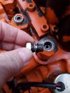
3. Cleaned the suction strainer/filter. It wasn't too bad, just some black bits on it. Def needed cleaning- here she is cleaned up:
20230501_130817.jpg

4. Onhooked the hyd cooler couplers to drain the cooler, was familiar with these as I just replaced the cooler
5. Replaced the Pilot circuit filter and it's o-ring, filled w/oil and reinstalled. It was probably a day or two overdue but didn't see anything major inside. It's the things I can't see to be worried about
20230501_130903.jpg

6. Wiped up the debris in the bottom of the oil tank. Wasn't clean, but I'm guessing it wasn't too bad
20230501_130727.jpg

7. Installed the temp sensor and cooler couplers and added about 25 gals of oil ($$$$)
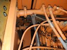
8. Installed a plug in the upper return port and took a plug out of the return line outside the tank. Clamped a piece of 1" hose on and ran that to a 5gal bucket.
20230501_125754.jpg

Intermission... I can only add 4 pics to a post.
 
Last edited:

skyking1

Senior Member
Joined
Nov 3, 2020
Messages
9,620
Location
washington
Don't start it until you are ready to bleed air off the top of the pumps.
On the JD 120 those plugs took a big wrench and cheater pipe.
 

NRath

Active Member
Joined
Mar 16, 2023
Messages
25
Location
Central VA
Next up...
20230501_125835.jpg
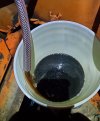
9. Started her up and let the system dump 10 gals into my dump buckets. That stuff came out looking the worst of all the oil. Or, maybe it was just getting dark. That oil def seemed worse than the rest. Anyway, it started to clear up at about 7-8 gals.
20230501_132131.jpg

10. Undid my flushing set-up
11. Dropped in the new return filter with it's new o-ring on the cap, bolts torqued to 40 ft-lbs
12. Topped off the oil, cycled some cylinders, and closed her all up.
20230429_225214.jpg

It was a nice little piece of maintenance to have out of the way. Expensive as he!!, but I know what's in there now. Hopefully I haven't screwed something up to send myself down another rabbit hole.

Alright- go ahead and put the rookie on blast!
 
Last edited:

NRath

Active Member
Joined
Mar 16, 2023
Messages
25
Location
Central VA
Don't start it until you are ready to bleed air off the top of the pumps.
On the JD 120 those plugs took a big wrench and cheater pipe.
I looked at that as a concern, but since the pump supply tube on the bottom of the tank stayed full, when I refilled the tank, no air should have been introduced to the pump.

Crazy talk?

The pilot side would have had a little bit of air in it, but there aren't any bleeders on the filter housing so I figured it would just push the air through and back to the tank eventually. When I started it, the pump and valve body never made any odd sounds like it was pushing major air or maybe cavitation.
 

NRath

Active Member
Joined
Mar 16, 2023
Messages
25
Location
Central VA
I thought about unhooking the pump supply tube to drain it but I had that air to the pump problem in mind and figured that gallon was better off staying in.

Thoughts?
 

NRath

Active Member
Joined
Mar 16, 2023
Messages
25
Location
Central VA
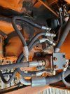
Pic from another day...
20230501_134453.jpg
20230501_134849.jpg

One of my errors may be that I need to pull of the pump regulator or whatever that almost rusty conversion thing on top is. Will I have to drain the tank below the height of that regulator to take it off? Is there an O-ring or two between that regulator and the pump? That's my biggest remaining leak to tackle.
 

skyking1

Senior Member
Joined
Nov 3, 2020
Messages
9,620
Location
washington
Yes that will do two things:
1) IT will gravity out, so drain the right amount of oil.
2) It will serve to burp any remaining air out of the pump too, IMO. Win-Win!
 

NRath

Active Member
Joined
Mar 16, 2023
Messages
25
Location
Central VA
Any idea if there are o-rings between there? Seems like there would have to be but I know that's an aftermarket kit. And, that's the lack of a rubber seal is the only reason it makes sense that there is RTV pushing out from under it. I've looked at several different ads for the part, but none of them show the bottom of it.
 
Top