• Thank you for visiting HeavyEquipmentForums.com! Our objective is to provide industry professionals a place to gather to exchange questions, answers and ideas. We welcome you to register using the "Register" icon at the top of the page. We'd appreciate any help you can offer in spreading the word of our new site. The more members that join, the bigger resource for all to enjoy. Thank you!

Mysterious Hydraulic Activity Cat 320L

Logan

Well-Known Member
Joined
Aug 30, 2010
Messages
98
Location
New Zealand
Occupation
Logger excavator operator and dad.
Hoping somebody can assist, I'm sure I read of someone here with a similar issue but couldn't locate it in the search. Was walking the old girl up a hill today and it staggered almost to a stall but then when I opened the grapple (bucket ram controls) it picked up speed. Carried on up the hill opening and closing grapple and it sort of jerky bunny hopped its way up there. What causes this? Thanks for listening.
 

Bob/Ont

Senior Member
Joined
Sep 18, 2012
Messages
1,605
Location
Ontario
Get a parts book so you can find the NFC valves in the main control body. Pull them out and clean them. Sounds like the NFC pressure is high and destroking the pumps as if controls where in hold.
Later Bob
 

Mobiltech

Senior Member
Joined
Jan 14, 2014
Messages
1,702
Location
Sask.
Occupation
Self employed Heavy duty mechanic
When you say stall do you mean engine stall or track stall.
If it was track stall it may have been sticking in high track mode and not shifting to low.
 

Logan

Well-Known Member
Joined
Aug 30, 2010
Messages
98
Location
New Zealand
Occupation
Logger excavator operator and dad.
Thanks Mobiltech, it pulls the engine revs way down and stops it dead if I'm not careful.
 

Bob/Ont

Senior Member
Joined
Sep 18, 2012
Messages
1,605
Location
Ontario
Logan, the pump controls can get worn and leak internally. If this happens pump control will be lost. Take the NFC lines off the controllers and plug them. Then have some one work the machine and look for leakage coming out of the controller, only a small drip should come out.
Later Bob
 

Mobiltech

Senior Member
Joined
Jan 14, 2014
Messages
1,702
Location
Sask.
Occupation
Self employed Heavy duty mechanic
You should also check your prv pressure. You may have a failing prv solenoid.
When you cycle the grapple you are putting both tracks onto one pump rather than two. Cycling the grapple puts the other pump under lighter load freeing up some engine horsepower.
The early 320s would stall out if the prv was not destroking the pumps properly.
 
Last edited:

Logan

Well-Known Member
Joined
Aug 30, 2010
Messages
98
Location
New Zealand
Occupation
Logger excavator operator and dad.
Sourcing a manual is proving problematic. I could buy a half decent car for the prices quoted. cat 320 block.jpg is the nfc one of these?
 

Logan

Well-Known Member
Joined
Aug 30, 2010
Messages
98
Location
New Zealand
Occupation
Logger excavator operator and dad.
cat 320 pump1.jpg Or is it one of these? There is a few drips coming out of the nylon plugs on this unit when she starts to get a sweat up. Be appreciated if somebody could tell me where the prv is too. Thanks.
 
Last edited:

Mobiltech

Senior Member
Joined
Jan 14, 2014
Messages
1,702
Location
Sask.
Occupation
Self employed Heavy duty mechanic
The prv pressure tap is the one under the black rubber cap on the left side of the picture of the pumps in post 9. The pressure here should fluctuate with engine load going higher under heavier load. It can be tested with a 600 psi gauge. It will run in the 50 to 400 psi range.
 

Mobiltech

Senior Member
Joined
Jan 14, 2014
Messages
1,702
Location
Sask.
Occupation
Self employed Heavy duty mechanic
The NFC lines are also on post 9. They are the ones going into the caps on the left side of the picture.
 

Logan

Well-Known Member
Joined
Aug 30, 2010
Messages
98
Location
New Zealand
Occupation
Logger excavator operator and dad.
Having never dismantled one of these NFC or PRV's before how much of it needs to be removed and what is usually used to clean them? Thanks.
 

Logan

Well-Known Member
Joined
Aug 30, 2010
Messages
98
Location
New Zealand
Occupation
Logger excavator operator and dad.
Had a few attempts at removing prv, worked out it needs a deep socket so heading off to the big smoke to get one tomoro. Can anybody tell me what I am likely to find once it is undone? No springs waiting to fly out hopefully? What is generally the procedure for cleaning a prv? How can you tell if it is ok, too dirty or knackered, without a gauge? Is it possible to test it off the machine?
 
Last edited:

Bob/Ont

Senior Member
Joined
Sep 18, 2012
Messages
1,605
Location
Ontario
The only way to check it is with a gauge hooked up and put it in the SWEEP mode. In that mode the ecm sends it the full range of voltage and the gauge should read the specified range of pressure. If it will deliver the full sweep then it likely only needs calibrating. If you change a valve it needs to be calibrated. You need a copy of the Hyd Test&Adjust manual for this work. I just re read this thread and get the feeling the PRV wire might be broken, that will stall the engine, the thumb circuit has flow cut back when used. That might be why you can travel when using it, the aux circuit control rather than the PRV is cutting back pump flow and reducing load on engine. To check this, unplug the PRV and try it to compare operation. If it's the same broken wire if worse calibration is needed.
Later Bob
 
Last edited:

Logan

Well-Known Member
Joined
Aug 30, 2010
Messages
98
Location
New Zealand
Occupation
Logger excavator operator and dad.
Hmmm, okay, Thank You Bob. anybody got a photo of the dash for 320L? I have the buttons but no icons or words except 'lights' which the previous owner was gracious enough to leave on there. Also if somebody could please share the relevant parts of the Hyd test and adjust manual. Also, what I have been told is the prv has no wires to it. Thanks.
 
Last edited:

Bob/Ont

Senior Member
Joined
Sep 18, 2012
Messages
1,605
Location
Ontario
Look around for a harness with a plug that will fit onto the PRV solenoid. That's your problem.
Later Bob
 

Logan

Well-Known Member
Joined
Aug 30, 2010
Messages
98
Location
New Zealand
Occupation
Logger excavator operator and dad.
Thanks Bob,

I gather the prv is in post 9 and the prv solenoid is in this photo. cat 320 block.jpg

The top solenoid has a hose near it that goes over to the left side of the pump where I'm told the prv is located. I cut the wires off this solenoid today and she didn't like it. Stalled with less load while lifting the boom. Hooked wires back up and it was better but still bogging down bad. Prior to this I found that the solenoid below the prv solenoid had a faulty earth. Re-routed the earth and it is getting 24.6 volts. This had no effect on machine performance. The prv solenoid is getting 6.3volts.
 
Last edited:

Mobiltech

Senior Member
Joined
Jan 14, 2014
Messages
1,702
Location
Sask.
Occupation
Self employed Heavy duty mechanic
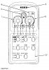
Here is the monitor panel layout.
Electronic Monitor Panel (Calibration Mode Start-up)
(1) Engine coolant temperature gauge. (2) Fuel gauge. (3) Action lamp. (4) Character display. (6) Hydraulic oil temperature gauge. (8) Air heater indicator (2DL and 9KK machines only). (9) Charge alarm indicator. (10) Engine coolant temperature alarm indicator. (11) Hydraulic oil temperature alarm indicator. (12) Engine oil pressure alarm indicator. (13) Controller alarm indicator. (14) Monitor alarm indicator. (37) Service switch.

1. Depress service switch (37) and start the engine. As shown in the chart above, the engine does not need to be started to obtain information for certain functions in the "Calibration Mode".


2. Continue to depress service switch (37) until action lamp (3) comes ON and character display (4) displays [20H] or [20C]. All the alarm indicators except character display (4) will turn OFF.


3. The "Calibration Mode" is now accessed and character display (4) displays the first of the 10 functions (machine and engine model numbers) as shown in the chart above. Action lamp (3) remains ON during all calibration function modes.


NOTE: Activation of the "Calibration Mode" overrides the function of engine coolant temperature gauge (1), fuel gauge (2), action lamp (3), hydraulic oil temperature gauge (6), air heater indicator (8), charge alarm indicator (9), engine coolant temperature alarm indicator (10), hydraulic oil temperature alarm indicator (11), engine oil pressure alarm indicator (12), controller alarm indicator (13), and monitor alarm indicator (14).


Calibration Of Proportional Reducing Valve

NOTE: This calibration procedure must be performed when either the proportional reducing valve and/or the controller has been replaced. This procedure is made at two power shift pressure points of 5 kgf/cm2 [490 kPa (72 psi)] and 25 kgf/cm2 [2450 kPa (355 psi).

View Image


Main Pump Compartment
(40) Power shift pressure tap.
1. Stop the engine and install a 4900 kPa (700 psi) pressure gauge to power shift pressure tap (40).

2. Make sure that the pump control backup switch is in the "AUT" position.

3. Start the "Calibration Mode". Refer to the section "Calibration Mode Start-up".

NOTE: The engine must be running and have a hydraulic oil temperature of approximately 50°C (122°F) to perform this calibration procedure.

4. Run the engine with engine speed dial switch at position "10".

NOTE: Activation of this calibration mode overrides the AEC function. If the engine speed dial switch is not at position "10" character display (4) will show an "E" in the first column. The engine speed must be corrected within specifications to continue the calibration procedure.

View Image


Electronic Monitor Panel (Calibration Of Proportional Reducing Valve)
(4) Character display. (27) Travel speed LOW (tortoise) indicator. (28) Travel speed control switch. (31) AEC switch. (34) Washer switch. (36) Alarm cancel switch.
5. Depress travel speed control switch (28) until travel speed LOW (tortoise) indicator (27) comes ON.

6. Character display (4) now displays [1 0]. The "1" indicates that the first calibration point has been accessed and the "0" indicates that the middle step of the 19 individual calibration steps has been accessed. Each step will change the power shift pressure by approximately 50 kPa (7.5 psi).

7. To change the power shift pressure:

a. To increase the power shift pressure, depress AEC switch (31) once. This will change character display (4) to [1 1]. Each time AEC switch (31) is depressed, character display (4) increases by one until character display (4) displays [1 9]. Also, the pressure reading at power shift pressure tap (40) increases by approximately 50 kPa (7.5 psi) for each increase. The following is an example of character display (4) readings in increasing order:
* [1-9]
* [1-8]
* [1-7]
* [1-6]
* [1-5]
* [1-4]
* [1-3]
* [1-2]
* [1-1]
* [1 0] = Middle Step
* [1 1]
* [1 2]
* [1 3]
* [1 4]
* [1 5]
* [1 6]
* [1 7]
* [1 8]
* [1 9]
b. To decrease the power shift pressure, depress washer switch (34) once to lower the value displayed in character display (4). Each time washer switch (34) is depressed, character display (4) decreases by one in descending order until character display (4) displays [1-9]. Also, the pressure reading at power shift pressure tap (40) decreases by 50 kPa (7 psi) for each decrease. The following is an example of character display (4) readings in decreasing order:
* [1 9]
* [1 8]
* [1 7]
* [1 6]
* [1 5]
* [1 4]
* [1 3]
* [1 2]
* [1 1]
* [1 0] = Middle Step
* [1-1]
* [1-2]
* [1-3]
* [1-4]
* [1-5]
* [1-6]
* [1-7]
* [1-8]
* [1-9]
8. To set "Calibration Point No. 1", perform the following steps:

a. Depress washer switch (34) until the pressure reading at tap (40) is less than 490 kPa (72 psi).

b. Depress AEC switch (31) until the pressure reading at tap (40) increases to approximately 490 kPa (72 psi).

NOTE: Pressure adjustments must always be made as the pressure is being increased.

c. Depress alarm cancel switch (36) to store the data in the controller.

d. Once the data is stored in the controller, display (4) changes to [2 0], which indicates that the first calibration point has been accepted and the second calibration point can be performed. At this time, the character display flashing light mode will change to a continuous lighting mode.

9. To set "Calibration Point No. 2", perform the following steps:

a. Depress washer switch (34) until the pressure reading at tap (40) is less than 2450 kPa (355 psi).

b. Depress AEC switch (31) until the pressure reading at tap (40) increases to approximately 2450 kPa (355 psi).

NOTE: Pressure adjustments must always be made as the pressure is being increased.

c. Depress alarm cancel switch (36) to store the data in the controller.

d. Once the data is stored in the controller, display (4) will change to [1 0], which indicates that the second calibration point has been accepted and the controller has reset to the first calibration point.
 

Attachments

  • image.jpg
    image.jpg
    85.4 KB · Views: 215
Last edited:
Top