• Thank you for visiting HeavyEquipmentForums.com! Our objective is to provide industry professionals a place to gather to exchange questions, answers and ideas. We welcome you to register using the "Register" icon at the top of the page. We'd appreciate any help you can offer in spreading the word of our new site. The more members that join, the bigger resource for all to enjoy. Thank you!

K3V63DTP

Hffhvg

Active Member
Joined
Nov 9, 2023
Messages
39
Location
Slovenia
Hello!

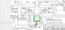
So I have a weak right track on my excavator. I have been doing some testing around this and narrowed down the problem to the pump. When switching the pump outputs the problem goes to the left, as well the boom gets weak and bucket, which makes sense according to this picture of pumps function from the diagram.

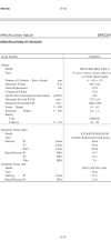
I wonder what the case drain spec is of this pump, because there isn’t one in the manual. I have been doing the calculation of 5% of pumps flow as according from the web. If I take the spec of pump flow from the manual or calculate it from the displacement by RPM I get the results of 10.66-14.96 litres per minute. So I would assume that about 13 litres per minute would be about it I believe.

Well anyways measuring the case drain I got 13 litres in half a minute, I then stopped the machine because the oil in sightglass dropped to the lowest point. This would mean my case drain is 26 litres a minute which would indicate some serious internal leakage.

My question is if my calculation would be correct. If it is I guess the pump is in time of immediate rebuild?

I just want to be sure if this test is reliable for analyzing the pump issues, because searching this forum I saw some information that the regulators can also be at fault. And high case drain can also be caused by some flushing valves? I am not sure if my pump has that.
IMG_3183.pngIMG_2917.png
 

KOBE STEEL

Well-Known Member
Joined
May 21, 2024
Messages
86
Location
.
You may need to take into account that the case flow may reach as much as 23 lpm at 2300 rpm engine speed, no pump load applied. This case flow comes from the pilot pump relief oil flushing into the pumps main case before going back to tank. Any internal pump bypass flow to case is additive to the flushing oil amount. The amount of flushing oil only applies to the type of pilot pumps that relieve internally. Kawasaki has both internal drain and external drain type pilot pump units for the K3V, K5V and K7V Series pumps.
 

Hffhvg

Active Member
Joined
Nov 9, 2023
Messages
39
Location
Slovenia
You may need to take into account that the case flow may reach as much as 23 lpm at 2300 rpm engine speed, no pump load applied. This case flow comes from the pilot pump relief oil flushing into the pumps main case before going back to tank. Any internal pump bypass flow to case is additive to the flushing oil amount. The amount of flushing oil only applies to the type of pilot pumps that relieve internally. Kawasaki has both internal drain and external drain type pilot pump units for the K3V, K5V and K7V Series pumps.
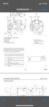
So on my pump there is only one case drain and is mounted on top of the PTO unit. Does this mean that pilot pump is draining internally combining the main pumps case drain?

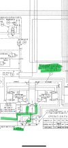
Looking at the schematic, I marked red the pilot pumps drain? Green being the main case drains? How much would the pilot pump then contribute to the leakage in my pumps when measuring?

IMG_3188.jpeg
 

Hffhvg

Active Member
Joined
Nov 9, 2023
Messages
39
Location
Slovenia
Please someone correct me if I’m wrong. Looking on my hydraulic schematic and taking everything I marked into account.

My two main pumps connect into the case drain on top of my PTO unit. I addition to that the pilot pumps drain is connected to it internally and when the relief pressure of pilot pump exceeds 3.9MPa it starts draining into the main case drain adding to the leakage. This pressure builds up because of dead headed flow because no operating function is being used.

Taking this into account my case drain flow of main pumps that would be 5% of 106.6 litres per minute times two is 4.264… Plus adding the pilot pumps flow which is 20.54 litres per minute that gets pumped through case drain would add up to about 25 litres per minute on the case drain without engaging any functions.

As by my approximate measurement of the case drain of 26 litres per minute could I say that the pump is running up to spec with minimum internal leakage?IMG_3189.jpeg
 

KOBE STEEL

Well-Known Member
Joined
May 21, 2024
Messages
86
Location
.
The main pumps internal leakage will increase as the load pressure on the main pump increases. These pumps have constant total horsepower control where the displacement of the main pumps will change under load so the volumetric efficiency will also vary. These pumps can typically give anywhere from 7 - 15 lpm of case leakage per pump at high load pressures of 4500 to 5000 psi, and a volumetric efficiency of around 75-85 % on pump input speeds of 1500-2000 rpm.
If you have isolated the issue to the main pump and would like to confirm if it is the pump then you could carry out flow testing providing the regulator adjustments have not been altered from factory settings or swapping the regulators to see if the problem tracks with one of the regulators instead of the pump. The regulators do have spring loaded feed back levers that must align onto a pin in the pump and this has to be done by feel alone. missing the alignment may result in a broken feed back lever and no flow control of the pump when the machine is started.
 

Hffhvg

Active Member
Joined
Nov 9, 2023
Messages
39
Location
Slovenia
I was thinking of swapping the regulator to see if the problem would switch to the other side. Do the hydraulic hoses that are connected to the regulator need to be swapped with the regulator or do they need to stay with the same pump they have been?

I don’t know if the regulator has ever been adjusted because I bought an used machine.

One thing I also wonder is that the pilot pump pressure should be 3.9MPa, but I measure it at 5MPa… Should I adjust its relief valve and lower it?
 

KOBE STEEL

Well-Known Member
Joined
May 21, 2024
Messages
86
Location
.
Hoses do not need to be swapped when crossing over the regulators. 3.9-4.5 should be a good range for the pressure of the pilot pump. 5 MPa would be the maximum pressure to allow. Mark with a paint pen and unscrew the pilot relief valve 1/2 turn and recheck the pressure.
 

Hffhvg

Active Member
Joined
Nov 9, 2023
Messages
39
Location
Slovenia
Hoses do not need to be swapped when crossing over the regulators. 3.9-4.5 should be a good range for the pressure of the pilot pump. 5 MPa would be the maximum pressure to allow. Mark with a paint pen and unscrew the pilot relief valve 1/2 turn and recheck the pressure.
The reason I am asking is because both regulators have one line coming somewhere from the control block I believe, but the rear one has additional hose that comes from the gear pump… So basically I just leave the hoses on the regulators and swap them?

A little bit more information about the condition of front pump…
Measuring the pressure the rear one is up to spec (a little short of 35MPa), while the front is only 25MPa.
When observing the arm-stick function I noticed that if I pull engage the pilot halfway when crowding I measure the pressure on front pump 30MPa. But if I engage it to the max the front pump only reaches 25MPa.
Does that make any sense? I would expect it to be the opposite.
 

KOBE STEEL

Well-Known Member
Joined
May 21, 2024
Messages
86
Location
.
Apologies, I did not see on your schematic the power shift pressure line from the sub pump. that hose connection supplies a signal to both pump regulators so if that hose cannot stay with the reg when swapping the regs over then you can remove and plug the hose and the fitting side on the reg can vent to atmosphere. The fitting should only drip a very small amount. you will not require this connection for your main pump test.
if you don't have any fittings to plug the hose and the hose is not long enough to go the front pump then you can remove the block and install it onto the other reg when swapping them over.
*Remember to fill the main pump casing will hydraulic oil after swapping the regs over.

when using the arm in pilot control with less than half of the pilot lever stroke, the arm circuit is supplied via one pump until you go over halfway on the lever, then the valve bank supplies oil flow from both pumps.
When only one pump is loaded with pressure the displacement of the pump remains relatively high but when both pumps are loaded together the displacement of both pumps will start to decrease so it can utilize the maximum amount of power from the engine. Pressure is a product of flow against a form of resistance so if you change the resistance or you change the flow rate, the pressure will also change. The pressure on both pumps should be equal when fully stalling the arm in circuit function or boom raise function.
 
Top