• Thank you for visiting HeavyEquipmentForums.com! Our objective is to provide industry professionals a place to gather to exchange questions, answers and ideas. We welcome you to register using the "Register" icon at the top of the page. We'd appreciate any help you can offer in spreading the word of our new site. The more members that join, the bigger resource for all to enjoy. Thank you!

Hitachi EX50URG

Sander85

Member
Joined
Jul 23, 2022
Messages
6
Location
New Zealand
Hi all,

I have recently purchased a EX50URG, having some issues with it at the moment.
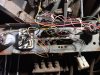
First is that by the looks of things almost all the original wiring has been cut and botched.
I had the issue that it would turn over but not start, after some investigation I have found that the ignition switch wasn't working properly.
It is connecting to the aux circuit when you turn the key but not to the glow plug circuit when cranking the engine over.
I assumed that the glow plug circuit would go from the ignition switch straight to the glow plug bar but,
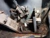
there is a thick cable from the battery + to the glow plug bar that has a interrupter switch that gets 'turned' on when you turn over the ignition switch.
Does anyone have a wiring schematic for this type digger as I will need to and want to redo the original wiring loom.
at this point only the battery light is working everything else has been cut and stripped.
the fuse box is completely disconnected, plugs and parts of the loom are missing. gauges not working etc.

Also having some issues with overheating but I am suspecting the radiator to be blocked most likely, this is the next problem to be tackled along with repairing the exhaust muffler.

Even tho there are some issues I do like this piece of equipment and hope it will serve for a while to come once I get the issues sorted.
 

uffex

Senior Member
Joined
Jan 23, 2012
Messages
4,464
Location
Lincoln UK
Occupation
Admin
good day
This is the nearest I have hope it helps out.
Kind regards
Uffex
 

Attachments

  • Z30:35:40:50 Leccy.pdf
    3.5 MB · Views: 15

007

Senior Member
Joined
Dec 28, 2016
Messages
282
Location
Australia
Hello Sanders85,
I think your assumption of the Glow circuit is incorrect.
The glow circuit has become complex in recent years and often the trend is to not have the glow plugs energized when cranking.
If that PDF is correct for your machine the ignition switch sends a signal to the glow controller which has a relay which passes the power onto the glow plugs.
The glow controller circuits are so blurry and hard to read its a task figuring out the intent.
Just generally they usually measure engine block temperature and decide whether glow is even needed.
They usually have a time limit on the energize time to protect the glow plugs.
There is probably more parameters involved.
Manufacturers seem to think operators are to stupid to understand glow plugs but in the old days all we had was a small bezzel on the dash and
if you wanted glow plugs you pressed the glow button until a resistance wire begun to glow in the bezzel and then you cranked the engine.
The glowing wire was to give the operator an idea how hot the glow plugs would be.
This system worked fine for many years.
If I was you and was faced with a totally messed up machine making them a manual push button in the cab might be an option.
All the best.
 

Sander85

Member
Joined
Jul 23, 2022
Messages
6
Location
New Zealand
Hello Sanders85,
I think your assumption of the Glow circuit is incorrect.
The glow circuit has become complex in recent years and often the trend is to not have the glow plugs energized when cranking.
If that PDF is correct for your machine the ignition switch sends a signal to the glow controller which has a relay which passes the power onto the glow plugs.
The glow controller circuits are so blurry and hard to read its a task figuring out the intent.
Just generally they usually measure engine block temperature and decide whether glow is even needed.
They usually have a time limit on the energize time to protect the glow plugs.
There is probably more parameters involved.
Manufacturers seem to think operators are to stupid to understand glow plugs but in the old days all we had was a small bezzel on the dash and
if you wanted glow plugs you pressed the glow button until a resistance wire begun to glow in the bezzel and then you cranked the engine.
The glowing wire was to give the operator an idea how hot the glow plugs would be.
This system worked fine for many years.
If I was you and was faced with a totally messed up machine making them a manual push button in the cab might be an option.
All the best.

Hi 007,
That pdf is not correct for my machine but I thought it would give me a fair idea of how it should be set up.
I don't think my ex50 had this same set up though, but since most of the original is missing it makes it hard.
What they have done with the wiring is quite worrying as a lot of it is showing exposed wire and melted through, and how they have set up the glow plug circuit is a bit backwards as well.

but after taking things further apart as I am trying to dig out what's left of the original loom
you can see on the photos the back of the dash panel and on the 2 other photos you can see the old cut loom and a couple of old relays, also the old fuse box is still in there but doing nothing.
What I can see is that they have used a 7core trailer cable to connect the bare minimum to have the digger running.
But it will not start without the pre glow so I will need to either do as you suggested and have a button on the dash or put in a timer relay which shouldn't be to hard

Cheers Sander
 

Attachments

  • 20220724_142754.jpg
    20220724_142754.jpg
    2.7 MB · Views: 10
  • 20220724_142754.jpg
    20220724_142754.jpg
    2.7 MB · Views: 8
  • 20220724_142805.jpg
    20220724_142805.jpg
    3.8 MB · Views: 8
  • 20220724_144214.jpg
    20220724_144214.jpg
    3.4 MB · Views: 8

007

Senior Member
Joined
Dec 28, 2016
Messages
282
Location
Australia
Looking at the photos I would give up on the original wiring and just do your own thing.
On my Kubota there is a glow light and some logic in there somewhere but the glows are not energized when cranking.
If you turn the key quickly to start the light just flashes on then off.
If in the dead of winter when the glows help i notice if you turn the key on and wait a moment the glow light comes on and goes out after about ten seconds so there must be a timer in there.
You do notice the difference in starting.
So a simple timer would get you out of trouble.
Make shore they still have some sort of fusible link or super large fuse in that glow circuit still.
If one of those glow plugs short to ground which they sometimes do the contacts in the relay fuse together and it will change the color of your day big time.
Cheers
 

Sander85

Member
Joined
Jul 23, 2022
Messages
6
Location
New Zealand
Looking at the photos I would give up on the original wiring and just do your own thing.
On my Kubota there is a glow light and some logic in there somewhere but the glows are not energized when cranking.
If you turn the key quickly to start the light just flashes on then off.
If in the dead of winter when the glows help i notice if you turn the key on and wait a moment the glow light comes on and goes out after about ten seconds so there must be a timer in there.
You do notice the difference in starting.
So a simple timer would get you out of trouble.
Make shore they still have some sort of fusible link or super large fuse in that glow circuit still.
If one of those glow plugs short to ground which they sometimes do the contacts in the relay fuse together and it will change the color of your day big time.
Cheers

Cheers,
Yes I will most likely be looking at a timer relay and redo a fuse box.
that's why I'm trying to find a wiring schematic for this digger so I know what needs to be fused etc.
The previous owner(s) have run the new wiring very poorly and it has been rubbing through in a lot of places arcing out, this is the main reason why I would like to recreate the original loom or as close to as I can and reinstate the dash lights etc.
The only thing working now is the battery light and hour meter. id like to get the fuel gauge and other things all back to working.
good thing there is no real urgency as it might take a bit of time
 

Sander85

Member
Joined
Jul 23, 2022
Messages
6
Location
New Zealand
I have managed to find a second hand loom for this digger, the people dismantling it did their best to tag everything where it came of to help me reassemble it back onto mine.
Still having some trouble with the puzzle, if anyone has a wiring schematic that is close to the EX50URG that would be helpful.

It will take a bit of time to sort it all out as my electrical knowledge has been under layers of dust since my school days lol

Second question would be that in this loom as well it looks like the wire from ignition to starter ( Green w Red tracer ) had been melted quite badly so ill replace that one to prevent further issues but what would have caused this? I saw the same issue on the makeshift loom, that one wire melted or overheated.
Just trying to prevent myself future issues.
 

007

Senior Member
Joined
Dec 28, 2016
Messages
282
Location
Australia
With regards to your second last post every thing has to be fused.
(Green w Red Tracer) is that power going from the starter B+ terminal to the ignition or power from the ignition switch to the starter solinoid start terminal?
The solinoid circuit often gets over loaded by faulty solinoids or if the battery is struggling the solinoid fails to pull in completely and stays on the pull in coil.
Most equipment with any sort of class have a relay in that circuit to take that load off the ignition switch.
 

Sander85

Member
Joined
Jul 23, 2022
Messages
6
Location
New Zealand
With regards to your second last post every thing has to be fused.
(Green w Red Tracer) is that power going from the starter B+ terminal to the ignition or power from the ignition switch to the starter solinoid start terminal?
The solinoid circuit often gets over loaded by faulty solinoids or if the battery is struggling the solinoid fails to pull in completely and stays on the pull in coil.
Most equipment with any sort of class have a relay in that circuit to take that load off the ignition switch.

The green with red tracer is going from the ignition switch to the solenoid start terminal. I went back and had a further look this evening and saw that the burnt out wire already has been replaced bit a new one.
I just think I am missing a half end from that new wire. I will renew that end and fuse it as well as a precaution.
Other than that as far as I can tell the rest of the looms looks good and original, I got the dash cluster with fuse box and relay's attached.
There's just a few connectors cut off where the thermostat, air flow etc would be which should hopefully be easy enough to put back in place.
Tomorrow is another day
 
Top