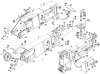
Atco- I have stared at the parts diagram of the telescope cylinder and I can't figure out the oil flow path. How does it work?
The crane has been working well it just leaks a few gallons of hyd oil every time I telescope in.
Is grinding out the weld, beveling the outer tube and re-welding not an option?
I live by the Blue Ash Airport not far from The Montgomery Inn.
"...not far from The Montgomery Inn." Darn it! :Banghead One of these days...I'm going to cross the Brent Spence Bridge...again.
How does it work? Well, I hope I can describe this.
All double acting cylinders have two oil chambers on each side of the piston inside the cylinder. One would be the cylinder barrel side, the other would be the rod side. To make the cylinder move in and out, it requires applying oil to either side of the piston. Most cylinders have fitting connections on the barrel to apply this oil to either side, your cylinder does not have this, because the barrel moves out with the mid section and the rod eye is pinned off and stationary. This makes the rod the stationary component and the barrel the moving component. So how do you get oil to either side of the piston with no connections to the barrel? Double wall cylinder rod. The rod is hollow, and there is a hole drilled in the rod where the piston is attached to the rod inside the cylinder. You just pump oil in this hollow rod, it comes out of the hole on the rod side of the piston, and this would make the cylinder retract. Now, how do we extend the cylinder? There is a tube in the very center of the hollow rod that creates a seperate passage from the hollow portion of the rod. This tube is welded to the rod eye block (where your holding valves are), it extends the length of the hollow rod, and is welded at the very end of the rod, on the barrel side of the piston. This makes an oil delivery path to supply oil to the barrel side of the piston.
To repair it? Like I said, I've never seen this happen before, so I'm a little in the dark on this one. Let's assume this; if you can telescope it in and out, that would suggest the welds on the inner tube are OK. Because if the inner tube was seperated at it's welds, well, the cylinder wouldn't operate properly. As for re-welding it? Honestly, I don't think I would attempt it. In this case, I would have a cylinder shop do this one. I want it done right. And I want it done right the first time. It will probably cost a few buck though. But that's what I would do. Just my humble opinion.
")