• Thank you for visiting HeavyEquipmentForums.com! Our objective is to provide industry professionals a place to gather to exchange questions, answers and ideas. We welcome you to register using the "Register" icon at the top of the page. We'd appreciate any help you can offer in spreading the word of our new site. The more members that join, the bigger resource for all to enjoy. Thank you!

D6C Front Idler Confusion.

Cub

Member
Joined
Apr 24, 2013
Messages
18
Location
United States
Occupation
Farm Manager
In February I bought a 1967 D6C Direct Drive Dozer serial # 74A2663. It started right up, had good oil pressure, No smoke to speak of, and sounded Good. The Chains, pads, and sprocket sections are like brand new. I should have lifted it up and checked out the bottom rolls. They're Junk. Both sides. No big deal as a complete set of NOS Rolls and 2 NOS Idlers were included in the sale. Like somebody started an undercarriage job but didn't for whatever reason finish it.
I did the Right side of the machine, to include Adjuster Seals. Easy Peasy. On to the Left side and the Track and Adjuster all came apart pretty easy. I find 6 Broken Bolts holding the Front Idler assembly together causing a Toe In situation resulting in uneven wear on the Idler itself. I Heated and Pounded, and Drilled, cussed some, and come to the conclusion, It ain't comin apart. The 4 Big Bolts holding the Idler Bearings came out fairly easy and it's lose and rolled ahead out of the way. The YOKE is the Issue. According to my Factory Service Manual, The Guys in the White Lab Coats removed the 2 Bolts on the end of The Recoil Rod, "Struck" it with a Hammer to separate it from the Yoke, slid the Rod out the Back and lifted the Yoke out to the Front. Yeah.... well that ain't happenin at my house. I beat on the Recoil Rod with a 12lb Sledge with limited swingin room, and it ain't comin apart. Probably never been apart since it was put together.

I got Mad... and Cut the Recoil Rod with a torch and got everything out on the ground. I know....Raised eyebrows and all. Here's the Delema. Parts book says I "Should Have" a Cat # 7M1844 Yoke. Stamped right into MY Yoke is #7M1775. Side Plates 7M1776. I'm thinkin best to put in the same new parts as the old ones that came out of it.
I have the correct Parts Book.

Service manual says that Recoil Rod will slide right in or out of that unit the Equalizer Bar and Forward Top Roll Mount to. Looks pretty tight to me.

Has anyone had experience with this procedure, or insight to these parts number discrepancies? The number 2P7984 has come up on my yoke search also.
Thanks in advance for any Wisdom sent my way.
 

obsolete

Active Member
Joined
Nov 25, 2021
Messages
28
Location
CA
7M1775 crosses to 7M1844, or 7M1775 is the casting number and 7M1844 is the assembly number, either way they are the same part.
 

Nige

Senior Member
Joined
Jun 22, 2011
Messages
29,424
Location
G..G..G..Granville.........!! Fetch your cloth.
7M1775 crosses to 7M1844, or 7M1775 is the casting number and 7M1844 is the assembly number, either way they are the same part.
7M1775 Yoke Assembly is cancelled and replaced by 7M1844.
7M1844 Yoke Assembly is made up of two parts. 2P7984 Yoke and 5L4398 Bolt.

I think that ties up all the Part Numbers you asked about.
 

Cub

Member
Joined
Apr 24, 2013
Messages
18
Location
United States
Occupation
Farm Manager
Yoke, Recoil Rod, and 2 New Wear Plates arrived along with a Bucket of Bolts. I had to remove the Equalizer Bar Support to install the Recoil Rod, but luckily all the bolts came out smooth. The Heads of the Support bolts were almost nonexistent. I welded some 1" Nuts on to the fragmented heads and they all came out clean. Yay Me.... All Bottom Rolls are installed. I got 2 NOS Front Idlers included in the sale. I'm going to change this one as it's pretty well worn thin on one side due to the misalignment caused by the broken Guide Plate and Collar Bolts.

The NOS Idlers are Dry. The Service Manual says to use a 5M2080 Nozzle to Inject Lubricant into the Reservoirs via a "Volume Compressor". Do I need to buy a Specialized Tool I'm going to use once, or is there another method someone has used to fill the shaft reservoirs?

I have 2 New Bearings and Locks coming and want to do this right.
Again, Any input is Greatly Appreciated.
 

Nige

Senior Member
Joined
Jun 22, 2011
Messages
29,424
Location
G..G..G..Granville.........!! Fetch your cloth.
The Service Manual says to use a 5M2080 Nozzle to Inject Lubricant into the Reservoirs via a "Volume Compressor".
That's pretty much the only way of doing it if the idlers are installed on the machine.

Are the plugs on the end of the idler shafts threaded.?
One thought is to lay the ilders on their sides and simply pour the oil into the hole. it will probably take a while for the air to work its way out. Just don't fill the cavity completely, you need a bit of air volume in there to allow for expansion when the oil heats up.
 

Cub

Member
Joined
Apr 24, 2013
Messages
18
Location
United States
Occupation
Farm Manager
Nige I was hoping you would chime in as you seem to know what you're talkin about Sir.
I'm a little forum challenged sometimes.

The NOS Rolls are All installed on the machine. I checked several of them prior to installation and they all had Oil in them.

The NOS Idlers are Not on the machine. The Plugs ARE Threaded, and I was looking for that 5M2080 Nozzle thinking it had to be pressurized in some way. It would be easy to lay the Idler flat and simply pour some oil in there if you think that would do it.
I just hate to buy specialized tools to be used once or go looking to borrow things.
Thanks.
 

Cub

Member
Joined
Apr 24, 2013
Messages
18
Location
United States
Occupation
Farm Manager
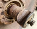
20230603_142200.jpgNige That's not gonna work as is. It probably would if the bearings were installed. There are two holes 1 on each side of the Shaft where the bearing fits into the Idler itself. With the bearings installed those holes would be covered and it would hold oil. Guess I'll just wait on the UPS Guy.
 

OzDozer

Senior Member
Joined
Jan 18, 2007
Messages
2,207
Location
Perth, Western Australia.
Occupation
Semi-Retired ..
Cub - There's no real need for the Cat 5M2080 Nozzle to fill the idlers and track rollers on this tractor with oil.
As Nige says, simply turn the idlers and rollers so the shaft is vertical, and slowly and carefully pour in the oil.
Of course, the idlers need to be fully assembled with the bearings and seals installed, before you do this.

The 5M2080 Nozzle is simply designed to get the oil going in, down to near the centre of the shaft, so the air being expelled can come out without blowing oil everywhere.
I seem to recall the 5M2080 Nozzle has an air release passageway built into it.

Simply use a small funnel and steadily trickle the oil in, and the displaced air will find its own way out of the filler hole, without oil blowback.
The idlers don't hold a great volume of oil, about a quart from memory (maybe less, it's been a long time since I last filled a D6C idler!).
The oil level is correct when the idler or roller is in its normal upright operating position, the shaft is level, and the oil is just trickling out of the filler hole.

There's a seal required under the head of that filler plug, this prevents oil weeping out. Slow oil leaks on idlers and rollers usually result in a destroyed idler or roller, as they run out of oil.
You really should check oil levels in idlers and rollers every 500 or 1000 hrs. You just remove the filler plugs, check that the oil is up to the threads, and if it's low, squirt more oil in with an oil can.
 
Last edited:

Cub

Member
Joined
Apr 24, 2013
Messages
18
Location
United States
Occupation
Farm Manager
Cub - There's no real need for the Cat 5M2080 Nozzle to fill the idlers and track rollers on this tractor with oil.
As Nige says, simply turn the idlers and rollers so the shaft is vertical, and slowly and carefully pour in the oil.
Of course, the idlers need to be fully assembled with the bearings and seals installed, before you do this.

The 5M2080 Nozzle is simply designed to get the oil going in, down to near the centre of the shaft, so the air being expelled can come out without blowing oil everywhere.
I seem to recall the 5M2080 Nozzle has an air release passageway built into it.

Simply use a small funnel and steadily trickle the oil in, and the displaced air will find its own way out of the filler hole, without oil blowback.
The idlers don't hold a great volume of oil, about a quart from memory (maybe less, it's been a long time since I last filled a D6C idler!).
The oil level is correct when the idler or roller is in its normal upright operating position, the shaft is level, and the oil is just trickling out of the filler hole.

There's a seal required under the head of that filler plug, this prevents oil weeping out. Slow oil leaks on idlers and rollers usually result in a destroyed idler or roller, as they run out of oil.
You really should check oil levels in idlers and rollers every 500 or 1000 hrs. You just remove the filler plugs, check that the oil is up to the threads, and if it's low, squirt more oil in with an oil can.
Thank You Sir, that's just how I intend to do it once seals and bearings are installed.
Do the Bearings need to be Pressed on, or gently tapped on with a Brass Hammer? Been cleaning the NOS Idler up with emery cloth and solvent.

No seal on the plug, but i have an assortment of brass oil pan drain plug washers and I'll find something that fits.

Thanks.
 

OzDozer

Senior Member
Joined
Jan 18, 2007
Messages
2,207
Location
Perth, Western Australia.
Occupation
Semi-Retired ..
Cub, the bushings/bearings need to be pressed in (carefully), because they're an interference fit, about .005" from memory. The cast iron bushing retainers will fracture if they're hammered.
 

Cub

Member
Joined
Apr 24, 2013
Messages
18
Location
United States
Occupation
Farm Manager
Cub, the bushings/bearings need to be pressed in (carefully), because they're an interference fit, about .005" from memory. The cast iron bushing retainers will fracture if they're hammered.
OzDozer Thanks. I wish my Service Manual went into a little more detail about this procedure. I don't have a Press big enough to hold that Idler, nor a Track Shop near by. I wonder if I blocked up the Idler under my Dozers Drawbar, inserted a Bolt to align the grove and used a Hydraulic Jack to push the Bearing down onto the Shaft, if that would work. Sounds Crude, but seems it would accomplish the task. How does one know how far to press the Bearing onto the Shaft? I assume when the Bolt slides in or out with no resistance. I'd hate to push it on to far....as I bet it's a pain trying to get if back off.
 

OzDozer

Senior Member
Joined
Jan 18, 2007
Messages
2,207
Location
Perth, Western Australia.
Occupation
Semi-Retired ..
Hold on, I'm getting a little confused here. I was talking about pressing the bearings (the bronze bushings) that run on the shaft, into position into the idler.

But reading back up the posts, you appear to say the idlers are fully assembled with the shaft in them.
So, when you're talking "bearing", I'm now presuming you're actually talking about the bearing blocks that are installed on the ends of the idler shaft? Is that correct?

They shouldn't be a press fit, they just slide on (tap fit) and tightening the bolts through the bearing block holds the idler shaft tightly in position. These blocks are cast steel, not cast iron as the idler bronze bushing supports/retainers are.

There are two idler positions for those bearing blocks, altered by rotating the blocks (thanks to an offset idler shaft hole).
There's a "high position" and a "low position", which respectively keep the idler "high" in relation to the track frame and track, and "low" in relation to the track frame and track.
Once the idler guide plates are installed, you can see whether the idler is in the high position or low position, by the position of the filler plug through the "window" in the idler guide plate.

The "low" idler position is for when you're dozing or using front-mounted equipment. This position means the idler is supporting the front of the tractor better - it stabilises the tractor, and increases the ground contact area.

The "high" position is for when you're using drawbar-attached or rear-mounted equipment, such as rear-mounted rippers. The high position makes for easier steering, and reduces idler wear (as compared to the low position).
 

Cub

Member
Joined
Apr 24, 2013
Messages
18
Location
United States
Occupation
Farm Manager
OzDozer. "Tap Fit" are the 2 Best Words I've heard today. Sorry if I was confusing in my description of what I've got going on here and am trying to do. Had that problem all my life.... especially with Girls.

My NOS Idlers are what I would call, Fully Assembled. The Shaft is IN and [Collars?] are Bolted in Place.
I was referring to the Bearing "Blocks" that attach the Idler to the Yoke and asking if They were a Press Fit. I'm glad to hear they can be "Tapped" into place.

I read up on the Positioning, High vs Low and get it. The Old Idlers were attached in the Low position, and I will put it back together as it came apart.

The Shaft is Tight in the Old Idler I'm replacing and spins freely. Very little if any side to side play and the internals are in good shape as far as I know. One side of it is worn down due to the misalignment issue and I going to keep it as a spare and reface it with the welder at some point. I like to weld and we just bought a New Wire Feed.

Thanks for sharing your knowledge.
I'm just waiting on parts.
 

OzDozer

Senior Member
Joined
Jan 18, 2007
Messages
2,207
Location
Perth, Western Australia.
Occupation
Semi-Retired ..
Good, I'm glad we're on the same page now. Clean up the ends of the idler shaft where the bearing block slides on with some emery cloth to ensure you've got nice clean metal to assist the fitment.

Make sure you use nickel anti-seize on the shaft, and on all bolts in the undercarriage. If you don't thank yourself at some future disassembly date, then someone else will.

The bronze bushings in the idlers and rollers can have a lot of movement (play) in them, and still be quite serviceable. I seem to recall .050" is the maximum bronze bushing to shaft clearance.

When you re-install the idlers, run a string line along the centre of the track rollers and sprocket to ensure the idler is positioned in line with the rest of the track components.

Also, check your track frames for misalignment by measuring the "toe out" between front and rear.
When the sprocket hub bushings get worn, the track frames splay out and this creates unnecessary wear levels in the undercarriage, and wastes fuel and HP.

Track frames get bent, too, so check them for damage. Slight bends are O.K., but bigger bends add to undercarriage misalignment. The inner diagonal braces of the track frame can also bend and cause vertical misalignment.
This happens when operators get rough and careless, and beat the tractor around over rocks and stumps, and by going too fast in rough conditions.

Cat had to strengthen the diagonal braces on the early D6C by plating them top and bottom, this did this free for all early D6C owners.
 
Top