
-
Thank you for visiting HeavyEquipmentForums.com! Our objective is to provide industry professionals a place to gather to exchange questions, answers and ideas. We welcome you to register using the "Register" icon at the top of the page. We'd appreciate any help you can offer in spreading the word of our new site. The more members that join, the bigger resource for all to enjoy. Thank you!
You are using an out of date browser. It may not display this or other websites correctly.
You should upgrade or use an alternative browser.
You should upgrade or use an alternative browser.
D5B Hydraulic Pump Rebuild
- Thread starter Ferdinand
- Start date
Ferdinand
Active Member

Finished the pump re-assembly tonight. Hopefully some of this info will hel someone else down the line. Everything below is verified information, as in I used the parts listed / measured it myself.
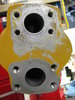
Pump: 3G4661, part of the 8J6330 Hydraulic pump assembly. Listed as "Type 2" in my old parts book for 153 hydraulic system for a D5B.
Pump part number is stamped on the rear of the case between the inlet / outlet ports.
Inlet is a code 61 -24 size 1.5" and outlet is a code 61 -20 size 1.25".
O-ring seal for the two case halves is a Dash 156 size, 3/32 thick. Viton replacement from McMaster is PN: 1288N253
Oring for the pump to engine accessory case is a Dash 250 size, 1/8 thick. Viton replacement from McMaster is PN: 1288N268
The two lip seals for the inlet shaft are 2.0" OD, 1.25" shaft dia and 0.43" thick. Made of Viton with hard sealant on outer sides. Current seals from CAT are made by SKF.
Rotor plate seals can be made from Viton oring cord stock of 1/8" (0.139" actual) thickness. As the original seals are pre-shaped, using the cord stock can be challenge since it wants to spring out of place or deform the plastic carrier and push it into the way of the rotor bushings during case assembly.
The rotor bushings appear to be teflon coated.
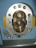
The pump stack up consists of a 4 piece seal set, an end plate made of steel with bronze facing the rotors, the rotors themselves, a top end plate and another 4 piece seal set.
The seal sets consist of an aluminum spacer, a thin clear plastic holder for a rubber seal, a formed rubber seal and a hard plastic backing plate. The thin clear holder has a U cross section to hold the oring like rubber seal.
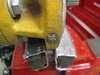
The pump uses two stacked lip seals to keep the hydraulic fluid out of the engine. The back of the first seal is vented to the pump inlet to limit the pressure seen by the seal. There is a spacer between the seals and a groove cut into the case so that any oil making it past the first seal should be vented to a drain hole at the bottom of the front of the housing and outside of the engine. This drain hole has a very small valve in it, with a spring loaded check ball to try and keep dirt out. The valve's two exit ports are located at the sides of the valve, which looks like a bolt with a hex head. It's pressed into the body, though it would appear to be screwed in at first glance. The drain holes get plugged almost immediately making this vent almost useless. Even though my seals were leaking several gallons a day into the crankcase, not a drop came out of the vent.
There is enough space in the hole where the lip seals are pressed to seat new seals about 1/8"+ higher than normal, avoiding any wear groves that may exist on the input shaft. It is possible to re-sleeve the shaft with two sleeves, but it needs to be done after the housing is re-assembled as the sleeves won't with through the shaft bushing in the housing. Using the sleeves would of course require removal of them if the pump needs to be disassembled at some point.
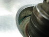
The input shaft has 22 splines with a 0.942 OD and 3/4" spline length.
My gear was loose on the shaft due to the spline being about 0.002" longer than the gear is thick. No obvious reason for this was visible. I put the heavy washer that holds the gear onto the shaft on a lathe and faced 0.010" out of center area where the shaft hit the washer to move the clamping force back to the outer edge of the gear.
The rotor end plates looked to be in good shape as did the rotors and housing so they were all re-used. There was an obvious casting void in the middle of rotor area in the aluminum housing. Seems the factory thought this was OK and used it anyway. No crack propagation or other defect expansion was visible.
All exterior hardware was replaced.
Total cost for the rebuild was just over $100.
Additional pictures in next message.
Attachments

Ferdinand
Active Member
More pictures...
Regarding the cost of rebuilding vs. replacement, my view has changed over time as I've been burned so often with aftermarket and OEM parts. The starter died on this machine and I first replaced it with a cheap aftermarket. That failed, stuck in the ON position, after the first start. Thinking I learned my lesson, I replaced it with a CAT rebuilt. That had parts falling off it within the first hour of run time. Luckily I had the guards still off and I noticed the missing solenoid cap. Seems that having enough threads for the cap to be installed with 1/4 turn was good enough for the rebuilder.
As the machine is in a very remote location, reliability is my number one priority, thus rebuilding things myself is actually a time saver since I know they are done right. Wish I didn't have to, but...
Attachments

Last edited: