• Thank you for visiting HeavyEquipmentForums.com! Our objective is to provide industry professionals a place to gather to exchange questions, answers and ideas. We welcome you to register using the "Register" icon at the top of the page. We'd appreciate any help you can offer in spreading the word of our new site. The more members that join, the bigger resource for all to enjoy. Thank you!

Cummins 8.3 roller camshaft replacement tooling - anyone have pics or specs?

treemuncher

Senior Member
Joined
Dec 31, 2006
Messages
1,179
Location
West TN
Occupation
eatin' trees, poopin' chips
My #5 intake lobe on my QSC 8.3 has thrown the rocker bridge a couple of times over the past 20 or so hours. The last time it did this, I measured and paid close attention to the amount of lift on the rack while running. #5 intake is down about 50% of similar lift by eyeballing it while running. Machine is at the shop and under disassembly to see if I either can change the camshaft with the motor in the machine or, if required, pull the entire engine to get this done. The engine has just under 5k hours on it and gets regular servicing.

During my research of this procedure, I see that Cummins specifies using tool number 3165088 to change out the camshaft and hold up or replace the lifters. These tool kits are more expensive than the parts I need to change out. Does anyone have some pictures or specs on this kit? I can build what I need here at the shop for a whole lot less than the $2k-$2.5k pricing that I have found for 12 tappet holders, tappet holding tube fixture and a few other pieces. I will pull the engine and flip it upright or upside down before I pay that much for a one time tool kit.
 

02SILVER

Well-Known Member
Joined
Apr 5, 2011
Messages
79
Location
Florida
We recently replaced the timing case on 8.3 that was cracked. We held the lifters up with wooden dowels that had an "x" cross cut in the end. This would pinch the lifter and pull it up, then rubber band it up to whatever was closest. This worked well for pulling the cam without pulling the engine.
 

treemuncher

Senior Member
Joined
Dec 31, 2006
Messages
1,179
Location
West TN
Occupation
eatin' trees, poopin' chips
We recently replaced the timing case on 8.3 that was cracked. We held the lifters up with wooden dowels that had an "x" cross cut in the end. This would pinch the lifter and pull it up, then rubber band it up to whatever was closest. This worked well for pulling the cam without pulling the engine.
That is the kit for the mushroom or sliding type lifters. That one is easy to DIY build a kit. I have the roller type lifters in my engine according to Cummins Quickserve when I looked up the engine build sheet. The roller type lifters take a different service kit that includes mechanical tappet holders and a special tray to insert the lifters into the cam bore.
 

treemuncher

Senior Member
Joined
Dec 31, 2006
Messages
1,179
Location
West TN
Occupation
eatin' trees, poopin' chips
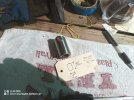
Ok, my tappets finally arrived a few days after the camshaft. For anyone else in this predicament, here is what the roller tappets look like and what the basic hole dimensions are.

IMG_20250811_100311_255.jpg

The 5/8" max access hole is the kicker here. I don't want to waste time building anything fancy. It would take some design and build time to copy something like the expensive tooling that is out there. You need something wider than the 5/8" max access to grip within the bore of the tappet if you want to build a gripper type holder. Instead, I ordered some N52 neodimium magnets and purchased some 6' sections of 5/8" dowel rods. These magnets are strong enough to hold, are encased in a steel pot and are just under 5/8" outside diamter. I was able to cut four 18" long dowels from each stock piece. The dowels were squared up, lightly tapered, center holed and pre-drilled for the wood screws that were included with the magnets.

Center hole
IMG_20250812_145011_972.jpg

Drill undersize
IMG_20250812_145501_826.jpg

Finished tool - 12 of these are required for this engine
IMG_20250812_145906_459.jpg
 

treemuncher

Senior Member
Joined
Dec 31, 2006
Messages
1,179
Location
West TN
Occupation
eatin' trees, poopin' chips
These tools grip better on the wider side than they do on the deepest part of the interior. You can feel the tappet rise and hold pretty tight before the magnet will let go. As of now, the camshaft is finally out. I will take some more pics in the AM.

IMG_20250812_151643_336.jpg
 

treemuncher

Senior Member
Joined
Dec 31, 2006
Messages
1,179
Location
West TN
Occupation
eatin' trees, poopin' chips
So this has become a major CF. I was unable to get the lifters to set in properly into the holes and line up the slotted follower. One of the new lifters got away from me and then eventually dropped into the oil pan. I did have ahold of it with a magnet and right there at the side of the block (oil fill) when I lost the magnet inside of the oil pan or engine. !@**, now the engine has to be pulled. Maybe 1.5" clearance under the oil pan inside of a bathtub - no other way to drop the pan. I will set the engine on the bell housing and install the lifters and cam while upright to make life easier.

The magnetic sticks worked great for pulling up the roller lifters and the tray tool that I made up worked fine for removal of the lifters, with the exception of the #5 intake which was the bad one. It took more serious persuasion to remove it and a special tray with an overbored hole for it to drop it.

The offensive lifter in the oversized pulling tray next to the main fabricated lifter tray. It was marred up enough that even when driven with a dowel and hammer, it did not want to fit into the standard tray.
IMG_20250813_114908_355.jpg

New lifters ready to ride into position. Unfortunately, I was unable to get any of those that I tried to get started into the bores and line up with the slot & follower.
IMG_20250813_120921_721.jpg

The lifter tray is nothing more that a handrail dowel with a flat side. Holes were bored through at 1.25" diameter. Pictured here on a final sanding and clean up prior to application of metal tape. Top side of tape trimmed with exacto knife to open the top. The tape is what makes the floor in the tool so that the lifter can sit as low as possible to slide through the camshaft bore while sitting upright. Hole locations were measure from the old camshaft. Old lifters were dropped into corresponding holes then rotated about 45 degrees to release magnet. With the exception of the trashed lifter, this went as smooth as possible for removal of lifters. Too bad install did not go as smooth.
IMG_20250813_095524_602.jpg
 

HarleyHappy

Senior Member
Joined
Sep 30, 2020
Messages
3,486
Location
So NH
Occupation
Welder/Mechanic
As much as I hate the time lost, making tools for a job, I try and remember how much stuff I have bent, broken or destroyed, with the wrong tools for the job.
 

treemuncher

Senior Member
Joined
Dec 31, 2006
Messages
1,179
Location
West TN
Occupation
eatin' trees, poopin' chips
For anyone else in this situation with a bad lifter & cam, be sure to check the follower pins. The bad lifter sheared off the follower pin on #5i or maybe the pin broke and allowed the lifter to rotate out of the correct position and lead to the destruction. The follower pins are accessed from the intake side of the block and take a 3.5 mm Allen tool. Pins run about $10 each. I have 12 new on order - no sense in taking any chances on worn pins at this point. The broken pin was in the oil pan. Everything else about the internals was very clean with the exception of some minor metal flakes in the pan from the destroyed lifter. Cylinders are nearly wear free.

IMG_20250817_140443_556.jpg

Flipping the engine onto the bell housing made installation of the new lifters a breeze compared to attempting the install with the engine in the machine. Installation of the camshaft was also much easier by holding it above the block with the forklift and using a ratcheting chain hoist to lower it gently with precision. Be sure to make a solid fixture attached to the bell housing to prevent anything less than a solid ground mount if the head and other components are still attached. I bolted up some 2x6 boards and a heavy block to support the head in order to make a simple fixture for this.

IMG_20250816_133553_899.jpg

Back to waiting on parts to finish the oil pan and a new rear main seal.
 

HarleyHappy

Senior Member
Joined
Sep 30, 2020
Messages
3,486
Location
So NH
Occupation
Welder/Mechanic
How are the motor mounts?
The lifters rotating are a problem on my GM 5.3 and then recommend that whenever you’re in the motor, to always replace the plastic lifter trays as with heat cycles and time, they open up a little and allow the lifters to turn.
This either shears the pins or damages them, so the lifters rotating will either not collapse and bend the pushrod and it causes premature cam lobe wear.
 
Last edited:

treemuncher

Senior Member
Joined
Dec 31, 2006
Messages
1,179
Location
West TN
Occupation
eatin' trees, poopin' chips
How are the motor mounts?
The lifters rotating are a problem on my GM 5.3 and then recommend that whenever you’re in the motor, to always replace the plastic lifter trays as with heat cycles and time, they open up a little and allow the lifters to turn.
This either shears the pins or damages them, so the lifters rotating will either not collapse and bend the pushrod and it causes premature cam lobe wear.
The right side rear mounts were bound up tight and stripped the rubber off of the steel center when I tried to pull the mount. I had to unbolt that mount from the side of the engine in order to pull the engine. I just got off of the https://www.mecanocaucho.com/en-US/amc-mecanocaucho/ website in order to purchase new mounts for the back end. I had pulled a couple from my burned parts machine and found the company logo from that set in order to determine what I had in the machine. Nothing else out there matched up. Glad I was able to source the originals.

The lifter alignment pins are installed from the outside of the block and are 100% steel. A couple of the other lifters felt like they had a little rotational slop compared to the majority of the others. Because of that slop, I figured for the price of $120 in parts, get it done now so I don't have to look back or worry about how they are. From what I have read, these pins normally don't break so I think that the fact of the lifter being trashed is what really caused the pin issue. I did not realize the first time the lifter bridge fell off was the lifter issue. I misdiagnosed it as a failed injector and changed it out without realizing that the bridge must have been off when I started disassembly to change out the injector. Another learning moment in life. That caused me to let the cam and lifter go longer than I otherwise would have. I do not like to push parts to catastrophic failure.
 

treemuncher

Senior Member
Joined
Dec 31, 2006
Messages
1,179
Location
West TN
Occupation
eatin' trees, poopin' chips
Old follower pins in red, new ones are a 2 piece design. They still measured the same depth with the calipers and already had thread sealant installed.

IMG_20250820_160035_762.jpg

Follower pins are easy enough to get to once the ECM and fuel pump are removed.

IMG_20250820_141635_081.jpg

Carefully swinging the motor from 90 degrees upright to horizontal to finish the oil pan gasket and the rear main seal that were leaking for a long time. The camshaft installation was much easier with the upright engine and slowly lowering it with the chainfall. In the end, it was well worth the extra effort to pull the engine. It needed the seals and new motor mounts anyways.
swing.jpg

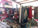
Engine and radiator nestled back into the frame. On its way back to working.

IMG_20250822_142305_347.jpg
 
Top