• Thank you for visiting HeavyEquipmentForums.com! Our objective is to provide industry professionals a place to gather to exchange questions, answers and ideas. We welcome you to register using the "Register" icon at the top of the page. We'd appreciate any help you can offer in spreading the word of our new site. The more members that join, the bigger resource for all to enjoy. Thank you!

Case relief valve disassembly....how is it done?

Glen Weldon

Well-Known Member
Joined
Aug 11, 2018
Messages
98
Location
Autauga County, Alabama
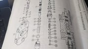
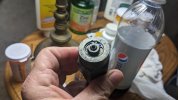
I have 8 of these to disassemble but I'm not sure exactly how it's done. I can't get the snap-ring out because the nut is in the way, and the nut won't budge. I figured while I was disassembling the entire valve I might as well replace those O-rings in these valves...if I can get them apart that is...

PXL_20231109_204555709.jpg
PXL_20231109_204610168.jpg
 

Glen Weldon

Well-Known Member
Joined
Aug 11, 2018
Messages
98
Location
Autauga County, Alabama
Well, I was fiddling with the snap ring using snap ring pliers, trying to work around the nut when the whole thing exploded! It is now disassembled. Now if I can find the snap ring!
 

melben

Senior Member
Joined
Jan 14, 2008
Messages
1,029
Location
Williamsport, Pa
Occupation
Retired 50 Yrs with Case dealership
If you disassemble these valves you must have them put in a fixture and reset to specs, our dealership has a fixture that you screw the valves into and use a handpump to reset them to spec. If they are to low the machine will not work to spec and if they are to high, cylinder barrels and rods, hoses and structural damage will ocour, do you suspect that one was bad ? Mostly just replacing the orings that you see is what is done, If you have reason to further disassemble them be aware of the proper procedure to set them up and having them reset will restore the digging power lost by aging springs inside the cartridges.
 

Glen Weldon

Well-Known Member
Joined
Aug 11, 2018
Messages
98
Location
Autauga County, Alabama
If you disassemble these valves you must have them put in a fixture and reset to specs, our dealership has a fixture that you screw the valves into and use a handpump to reset them to spec. If they are to low the machine will not work to spec and if they are to high, cylinder barrels and rods, hoses and structural damage will ocour, do you suspect that one was bad ? Mostly just replacing the orings that you see is what is done, If you have reason to further disassemble them be aware of the proper procedure to set them up and having them reset will restore the digging power lost by aging springs inside the cartridges.
Thank you for your reply. I am happy to be speaking to somebody who knows much more about this than I do. I have briefly read the manual concerning resetting the relief pressure on the valves. I do not have a hand pump nor a fixture, however I believe (correct me if I'm wrong) that it should be possible to reset these valves on the machine using a test gauge and applying force to the circuit? This would be the only way I have to adjust the relief pressure. If this isn't adequate, I'll find a dealer who has the appropriate equipment and take the valves to them. My nearest CaseIH dealer is 3 hours away.

As to why I would want to disassemble them, when I removed the spring from the only one I have yet to disassemble, it was packed with what I would call a grease-like jelly. Unless these valves are supposed to be packed with grease on the spring end, I'm assuming it was congealed hydraulic junk (water mixed with deteriorated O-rings and dirt plus hydraulic oil). Beyond that, both of the O-rings on the inside of the valve were extremely hard. No pliability left in them at all. I couldn't remove them without breaking them. Considering that the cast-in date on the valve body was 1973, this could quite possibly be the first time they have been disassembled. It definitely needed cleaning. I should have the proper O-rings on-hand by Monday so I can do the same thing to all of them.

Also, as far as the relief pressure setting, I am measuring the length of the setscrew that protrudes below the top plate with a dial caliper. I will reset the screw length to the same as it was before it was disassembled.

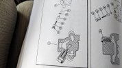
I have another problem that I don't know how to fix. In the return section of the valve there also is a relief valve. After removing this valve, there is a plunger in a hole. I can barely see the plunger inside the valve. I can't figure out how to remove it. In the inlet section there was also a plunger in a hole, but I was able to push on the end of the plunger and it came out. With the outlet section, there is no hole that I can access to push out the plunger. In the image below on the left-side diagram, I'm talking about item #15. In the cross-section you can see that there isn't any access to it opposite the spring. Any hint how to get it out?

PXL_20231110_202729062.jpg

Once again, thank you for your reply.
 

Glen Weldon

Well-Known Member
Joined
Aug 11, 2018
Messages
98
Location
Autauga County, Alabama
Just an addendum. The thing I called the "return" section above is actually called the outlet section. I brought it inside and while examining under a fairly bright light, I could just barely see the end of the plunger, Det. #15, through one of the ports. I used an O-ring pick, one of the types with several angles bent on the end like Harbor Freight sells...I snuck the tip of the pick on to the part of the plunger end that I could see and pushed! It took some pressure but it finally snapped out! I think it was rust seized a bit. It had a black stain on a portion of the plunger that I polished out with 1000 grit silicon carbide wet-or-dry paper soaked in diesel. After that, with just the right amount of wiggling, it went back into the hole with just the gentlest of a push. I was able to get it out the second time in an identical manner but it came out gently. That's a load off my mind.

Also, the rest of my O-rings came in today to finish the job. It's raining here, not hard, just enough to make it miserable to work in. I brought the boom section relief valve inside...the one pictured in one of the posts above. I washed it up with detergent, let it dry for about 4 hours, then I replaced all the O-rings and reassembled using just a touch of oil on all the seals. It feels good to have been able to cross-reference Case part numbers to actual standard O-ring "dash" numbers and be able to reinstall with no issues. I feel really good that the rest will go back together with minimal issues.

I tend to get long-winded. Sorry about that...
 

clueless2

Active Member
Joined
Oct 27, 2020
Messages
44
Location
Kerrville,Texas
No need for any apologies.
This has been a very informative thread for anyone with Case backhoe control problems.
Could you share with the members how you were able to to cross reference the Case part numbers to the ones on Grainger's website ??
 

Glen Weldon

Well-Known Member
Joined
Aug 11, 2018
Messages
98
Location
Autauga County, Alabama
Could you share with the members how you were able to to cross reference the Case part numbers to the ones on Grainger's website?
Thank you Clueless2 for your kind words. I have learned a bunch from people in this forum. It's great when people who know share what they know. Unfortunately this is my first real dealings with a real hydraulic system. I'm learning a bunch


As far as the cross-referencing, I will explain but if you have the same valve, it would be easiest to wait until I'm done and I'll post a list. The cross-referencing process is a very tedious, convoluted process that involves searching on the internet using the original Case part number in the parts manual. There are some web sites that will show the size of the O-ring along with the "dash" number, which equates to a specific standard size. I learned about dash numbers along the way because I've never dealt with O-rings before.

Once I found multiple sources to verify the dash size, which in some cases was nearly impossible, I searched the Grainger website for "O-rings". The results will show a row of O-rings at the top that are a sub-menu of what material you wish your O-rings to be. There are choices like Viton, which is great but really expensive. If you have not cost limitations, use this material, your seals will probably never need replacing in your lifetime. There are other materials. I used Buna-N which is a good, general all-round material that is resistant to petroleum products. Other choices are silicone, teflon (PTFE), neoprene, ect. I selected silicone for the in-between section seals because when installed, they are almost flat. I think Buna-N would probably rupture although the seals that come out looked like Buna-N, but I admit I don't know if other materials would look different. I would want these seals to remain pliable throughout their lifespan. The section O-rings I removed were hard as very hard plastic.

For those who have the same valve to rebuild, I will post all the cross-referenced part numbers for what I used. If you wish to use something other than Buna-N, the "dash" numbers will be the same but the Grainger part numbers will be different.

There are about 60 (61 exactly I think) O-rings required for the complete rebuild. Some of these O-rings are less than a dollar a piece but you have to order them in quantities of 50-100. The silicone rings are a bit more expensive. I am considering putting together complete rebuild kits and selling them for a fair (read fairly low) price. For that price I would label each O-ring as to where it goes, what dash number it is and the O-ring material. I would imagine that advertising and selling stuff here on the forums is discouraged or prohibited. If anybody would be interested in one of these kits, feel free to message me and we can discuss further.

If you would rather buy directly from Grainger, I can give a list. I'm going to wait until I have the valve all reassembled to make sure everything goes as planned before steering anyone down the wrong path.
 
Last edited:

Glen Weldon

Well-Known Member
Joined
Aug 11, 2018
Messages
98
Location
Autauga County, Alabama
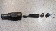
For those of you who haven't seen what a Case relief valve looks like, here's a picture that shows the body of the valve with all the components that go inside with fresh new O-rings. Some of the valves have a piece of steel rod inside the spring. I suspect this is to limit the travel of the plunger, but this is just a guess. Of course the components didn't look like this when they came out.

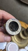
The second picture shows the inside of this same valve with the top cap removed. The top cap was stuck so bad that I had to take a punch and hammer and tap on it several times to break the crud free. There was nasty scum all in the spring that was like a jelly. I figured it was oil congealed with water and dirt.

PXL_20231112_235948675.jpg
PXL_20231112_233845866.jpg
 

1693TA

Senior Member
Joined
Feb 27, 2010
Messages
2,687
Location
Farmington IL
Occupation
FAA Radar Engineer, (Retired)
If you disassemble these valves you must have them put in a fixture and reset to specs, our dealership has a fixture that you screw the valves into and use a handpump to reset them to spec. If they are to low the machine will not work to spec and if they are to high, cylinder barrels and rods, hoses and structural damage will ocour, do you suspect that one was bad ? Mostly just replacing the orings that you see is what is done, If you have reason to further disassemble them be aware of the proper procedure to set them up and having them reset will restore the digging power lost by aging springs inside the cartridges.

Not to derail the thread at all but the mention of the relief valve calibration is exactly why I stomp so hard on counterbalance, or load holding valves on cranes, manlifts etc. I'm citing the reasons I don't do any work on cylinders containing these devices. I don't have the proper tooling to calibrate them afterward and the risk to both life, and equipment it too great to bear, (for me).
 

Glen Weldon

Well-Known Member
Joined
Aug 11, 2018
Messages
98
Location
Autauga County, Alabama
I don't see your message as derailing anything. I thank you for the comment. If you read the fourth post in this thread, that is where I detail what I'm doing to ensure the valves are set pretty-much how they were before I disassembled them. I don't know if these are the type of thing where 1/16th of a turn equals can mean the difference of a thousand pounds. Please let me know if you don't think that my method is adequate. As I have said above, if what I'm doing isn't going to be good enough, I'll see out a method to reset them properly. If I have to make a rig to set them, I'll do so. Thanks again for your post.
 

1693TA

Senior Member
Joined
Feb 27, 2010
Messages
2,687
Location
Farmington IL
Occupation
FAA Radar Engineer, (Retired)
It is easy enough to calibrate a relief valve if you can restrain the operand from operating. What I mean as example is chain a boom from moving while you monitor and adjust the relief valve for the function being worked on. Swing, curl, extend, retract, lift, drop functions can all have relief valve settings or they could all depend upon a system relief setting. Each machine is different. Each machine require different safety precautions taken to preclude getting hurt or worse.

You do need to be monitoring the loaded pressures while you adjust the settings as some respond exponentially to minute adjustments.
 

HarleyHappy

Senior Member
Joined
Sep 30, 2020
Messages
480
Location
So NH
Occupation
Welder/Mechanic
It’s not very hard to set a pressure relief valve. If I have a gauge set up and specs to set to. I have even done a few without a gauge just turn up till it’s bypassing and back off a little.
Some hydraulics like a 500 psi difference and as low as 250 psi.
Safety is number one.
If you find yourself always reaching the relief settings, maybe some adjustments need to be made to the operator.
The yellow grease crud always seems to be found in the valves, especially machines that work outside.
Gasoline cleans it up quite well.
 

melben

Senior Member
Joined
Jan 14, 2008
Messages
1,029
Location
Williamsport, Pa
Occupation
Retired 50 Yrs with Case dealership
Looking at your pictures you were wise to follow up on disassembling them, after a thorough cleaning and new Orings I would lightly grease the spring area to prevent rusting, The problem with secondaries is that most are set above main relief substantially, I have heard of people increasing the main pressure to above secondary setting then setting the secondary, I have never done that and I consider myself after many years capable of doing that if I did not have access to the proper fixtures, BUT, I believe I have the experience and knowledge to do it safely. If you use that method use just enough rpm to keep minimum flow against the secondaries as they are not a high volume relief and much flow will distort your PSI at popoff readings. The pressure settings are stamped into the flats on the cartridge if I remember correctly. Boom down pressure is much lower than the main pressure so that one could be set by that method without increasing main relief. When the C series first came out a common complaint was that the boom would squash out so it was impossible to raise the machine to swing yourself over a ditch and I increased many to satisfy operators concerns. I believe the valve you had the plunger issue with is the Regen section, they are very trouble free but can get you scratching your head if it sticks.
 

Glen Weldon

Well-Known Member
Joined
Aug 11, 2018
Messages
98
Location
Autauga County, Alabama
Looking at your pictures you were wise to follow up on disassembling them, after a thorough cleaning and new Orings I would lightly grease the spring area to prevent rusting, The problem with secondaries is that most are set above main relief substantially, I have heard of people increasing the main pressure to above secondary setting then setting the secondary, I have never done that and I consider myself after many years capable of doing that if I did not have access to the proper fixtures, BUT, I believe I have the experience and knowledge to do it safely. If you use that method use just enough rpm to keep minimum flow against the secondaries as they are not a high volume relief and much flow will distort your PSI at popoff readings. The pressure settings are stamped into the flats on the cartridge if I remember correctly. Boom down pressure is much lower than the main pressure so that one could be set by that method without increasing main relief. When the C series first came out a common complaint was that the boom would squash out so it was impossible to raise the machine to swing yourself over a ditch and I increased many to satisfy operators concerns. I believe the valve you had the plunger issue with is the Regen section, they are very trouble free but can get you scratching your head if it sticks.
Thank you for your post. I am assuming (maybe incorrectly) that the main relief valve(s) are at or near the pump or the loader valve. As far as I can tell, the inlet and outlet for the backhoe valve body have relief valves, but neither are adjustable. If the main relief valves aren't on the backhoe valve, I have not touched them.

Since you seem to be knowledgeable about the 580C valve, I have a question: On the bucket section, there are two additional relief valves bolted on to the section valve in addition to the actual section relief valves. This bolt-on section with two additional valves is not shown anywhere in my parts manual. I DID rebuild them...in as far as the components that needed O-rings seemed to be the same as all the others. I am just confused by the fact that this isn't shown in my manual. Do you know anything about these? I just reassembled and painted this section so I can't yet show a picture of it in context to the valve. It should be dry enough to touch tomorrow so I'll take a picture and post it...unless you already know about it and don't need a picture...

Edit: I was mistaken...it is the swing section that has the extra bolt-on part with two additional relief valves...
 
Last edited:

melben

Senior Member
Joined
Jan 14, 2008
Messages
1,029
Location
Williamsport, Pa
Occupation
Retired 50 Yrs with Case dealership
The main relief is in the loader valve, if you have service info you should be able to locate it. IIRC it is on the inside of the spools toward the operators platform facing front. should have an acorn nut on it. I am not familiar with the extra valves you are dealing with but the Commercial valves use on older machines had what they called criss cross valves in the swing section. Maybe something like that. I suppose it has something to do with the oil flows because of the geometry of the cylinder swing process. I'm just thinking out loud on that so don't take it to the bank!
 

Glen Weldon

Well-Known Member
Joined
Aug 11, 2018
Messages
98
Location
Autauga County, Alabama
The main relief is in the loader valve, if you have service info you should be able to locate it. IIRC it is on the inside of the spools toward the operators platform facing front. should have an acorn nut on it. I am not familiar with the extra valves you are dealing with but the Commercial valves use on older machines had what they called criss cross valves in the swing section. Maybe something like that. I suppose it has something to do with the oil flows because of the geometry of the cylinder swing process. I'm just thinking out loud on that so don't take it to the bank!
Funny you should mention the swing section. I don't know if you have followed my other threads about my backhoe hydraulics not working at all, but this whole problem started when I had the swing cylinders rebuilt. I left them sit for about 2 years before reinstalling them. When I did, I reversed the cylinders. Put the left on the right and vice versa. I figured this out when I didn't find a check valve in the proper place on the proper cylinder. When I checked the other one, there it was. I removed it and put it on the top connection of the left cylinder where the diagram shows it went. I racked my brain trying to figure out if the cylinders were the same of if they needed to be in a certain position. All reasonable thought tells me that it doesn't matter which cylinder goes where, just that the connections are as shown in the book. I have a nagging suspicion that when I get this valve rebuilt and reconnected, things still aren't going to work. The valve needed rebuilding anyway because it was leaking like a sieve, but I guess if it doesn't work after I reinstall it, I'm going to switch the places of the swing cylinders.

All of the lower portions of the relief valves, that is the two-piece assembly with the tiny spring between them and an O-ring... well, the O-rings were missing on all but one of them. I could reason that leakage from these relief valve may have caused things not to work, but actually it's just a reasonable guess. I've got a few commitments on Tuesday and Thursday but Tuesday morning I should be able to rebuild the last relief valve left to do. The biggest portion of what remains is all cosmetic. Although this machine looks like bloody hell, I can't in good conscience completely rebuild this valve without repainting it. It's fairly warm in central Alabama but I'm sure the paint won't dry well. The ones I painted today are curing in the shop. I have to clean the castings for 3 more sections. Also I can't remember if I ordered the wiper seals that go on top of the spool. I'll need to get some if I hadn't ordered them. Maybe they will com in sometime next week. It always takes longer than you expect, doesn't it?
 

melben

Senior Member
Joined
Jan 14, 2008
Messages
1,029
Location
Williamsport, Pa
Occupation
Retired 50 Yrs with Case dealership
Seems to! I do not believe there is any difference between the swings and I would not flip them, the restrictors being in the proper line is all that matters. Keep us posted and there are a bunch of good minds on here to guide you along, I do not mean to hog this one but I have many years in the shop dealing with these issues on older machines, there are issues on the newer machines that are above my pay grade level especially Power Shift electrical issues, and the new common rail emissions crap. I will happily defer to those way more qualified than I.
 
Top