• Thank you for visiting HeavyEquipmentForums.com! Our objective is to provide industry professionals a place to gather to exchange questions, answers and ideas. We welcome you to register using the "Register" icon at the top of the page. We'd appreciate any help you can offer in spreading the word of our new site. The more members that join, the bigger resource for all to enjoy. Thank you!

Case 680G backhoe project: squad

squad_1881

Well-Known Member
Joined
Aug 21, 2017
Messages
59
Location
Australia
Occupation
Architect
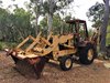
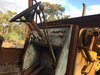
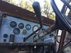
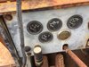
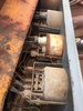
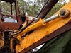
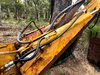
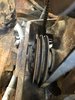
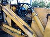
Here is the thread of another old machine, a Case backhoe 680G from year 1979 located in Australia. As it has been sitting for a while and therefore missing quite a bit, the intention is to bring it back to reasonably functional level to help out to build a new residence on the lifestyle block. Without knowing much of the history of the backhoe i can only speculate it is an ex government fleet and in some point of time sold to private hands whereas only the bare minimum has been done afterwards. Since i do not have a great deal of experience with that kind of equipment i have probably some stupid questions to ask and perhaps not so stupid one as well, hopefully everyone is fine with that.
 

Attachments

  • IMG_0084.JPG
    IMG_0084.JPG
    2.9 MB · Views: 141
  • IMG_0087.jpg
    IMG_0087.jpg
    1.8 MB · Views: 125
  • IMG_9762.jpg
    IMG_9762.jpg
    1.2 MB · Views: 124
  • IMG_0215.jpg
    IMG_0215.jpg
    1 MB · Views: 126

squad_1881

Well-Known Member
Joined
Aug 21, 2017
Messages
59
Location
Australia
Occupation
Architect
Comparing the dashboard images from the service manual and what this machine has, can anyone comment are those VDO gauges part of OEM product line made for Australian market or more likely aftermarket modification by someone else. Thinking of replacing all of those along the way when sorting out rest of the electrical things.
 

Attachments

  • IMG_9946.JPG
    IMG_9946.JPG
    903.8 KB · Views: 50

Ando

Well-Known Member
Joined
Nov 15, 2009
Messages
191
Location
Australia
Occupation
Proprietor - 5 Star Contract Services
Looks like someone has fitted them later. I did the same to my 580K after trying to track down a working dash (for a realistic price)
 

squad_1881

Well-Known Member
Joined
Aug 21, 2017
Messages
59
Location
Australia
Occupation
Architect
Looks like someone has fitted them later. I did the same to my 580K after trying to track down a working dash (for a realistic price)
I kind of leaning towards the same conclusion that things are not factory fitted, hence it looks too well and neatly done to be an aftermarket build lol.
 

Attachments

  • IMG_0732.JPG
    IMG_0732.JPG
    136.9 KB · Views: 44

squad_1881

Well-Known Member
Joined
Aug 21, 2017
Messages
59
Location
Australia
Occupation
Architect
Otherwise slow and steady progress fixing things up, both boom cylinders got repacked and some new hoses to there as well, few more cylinders to go, steering and front bucket ones are next in line. Also I noticed there is no engine oil refill cap, only a drain plug and large oil check dipstick, is that being used for the refill as well?
 

Attachments

  • IMG_0391.jpg
    IMG_0391.jpg
    378.4 KB · Views: 60
  • IMG_0390.jpg
    IMG_0390.jpg
    544.2 KB · Views: 55

squad_1881

Well-Known Member
Joined
Aug 21, 2017
Messages
59
Location
Australia
Occupation
Architect
Now was the time for the alternator to seize itself and snap one of the drive belts as well which were in the state of deterioration anyway. Trying to prepare things for the belt change though not sure how exactly to go from here. Apparently the big thing is to get the new belts around the crank pulley. Could someone comment from their experience what would the easiest way to do this. I am thinking of pulling the radiator and oil cooler out for easier access as i need to change fluids anyway, hence not sure how much work is it to do that, looks like a very tight fit in there though at least manual does not say that body panel frame needs to be removed and it should come off from the front. About getting the belt around the crank i am wondering is there a coupler between the hydraulic pump to slide it back and slip the belt in as i seen on 580 series or does the pump needs to pulled out completely on that machine, thanks. Also i take it has B type main v-belt and A type secondary one.
 

Attachments

  • 037FD1B8-15A0-4D6B-9B71-BC931ED49395.jpeg
    037FD1B8-15A0-4D6B-9B71-BC931ED49395.jpeg
    1.8 MB · Views: 59
  • 246D6DFC-309A-4B49-9CC4-6C048DF70BC3.jpeg
    246D6DFC-309A-4B49-9CC4-6C048DF70BC3.jpeg
    2 MB · Views: 58

Tinkerer

Senior Member
Joined
May 21, 2009
Messages
9,376
Location
The shore of the illinois river USA
The best way to change the belt is just like you are thinking. Drain the hydraulic oil tank first. There should be a steel hyd. line with tee in it midway on the left side of the frame next to the engine with a drain plug. Loosen the fill cap to remove tank pressure then screw it back in a couple of turns to prevent a huge gush of oil from coming out drain. Then remove the oil cooler, next drain the radiator. Raise the loader all the way and put the saftey locks on both hoist cylinders. loosen all the pipes and hoses on the hydraulic pump. Next remove the two big bolts that hold the pump on the front motor mount assembly so you can slide the hydraulic pump forward. Be sure to check the pump input shaft for any wobble that may be caused by a defective input shaft bearing. Most important next is check the splines on the shaft for excessive wear. The hub on the crankshaft damper will have an equal amount of wear.
The belts are a matched pair. I would recommend OEM belts from a CNH dealer.
 

squad_1881

Well-Known Member
Joined
Aug 21, 2017
Messages
59
Location
Australia
Occupation
Architect
The best way to change the belt is just like you are thinking. Drain the hydraulic oil tank first. There should be a steel hyd. line with tee in it midway on the left side of the frame next to the engine with a drain plug. Loosen the fill cap to remove tank pressure then screw it back in a couple of turns to prevent a huge gush of oil from coming out drain. Then remove the oil cooler, next drain the radiator. Raise the loader all the way and put the saftey locks on both hoist cylinders. loosen all the pipes and hoses on the hydraulic pump. Next remove the two big bolts that hold the pump on the front motor mount assembly so you can slide the hydraulic pump forward. Be sure to check the pump input shaft for any wobble that may be caused by a defective input shaft bearing. Most important next is check the splines on the shaft for excessive wear. The hub on the crankshaft damper will have an equal amount of wear.
The belts are a matched pair. I would recommend OEM belts from a CNH dealer.

Once again thank you for the advice Tinkerer, i think the direction is in there now and lets see how does it work out, will keep things posted.
 

Delmer

Senior Member
Joined
Jan 3, 2013
Messages
8,891
Location
WI
If there's any seepage on the crankshaft front oil seal, now's the time to do it while you're close...
 

squad_1881

Well-Known Member
Joined
Aug 21, 2017
Messages
59
Location
Australia
Occupation
Architect
Ordered new OEM belts and genuine Bosch alternator, not much chance that belts will arrive before the beginning of the new year. I take trying to remove the hydraulic pump coupler is the first attempt to make a gap for the belt and if this does not work then the pump itself has to be pulled forward, by the looks of it similar scenario like 580 series belt change, double amount of coupler bolts though.
 

Attachments

  • 001_coupler.JPG
    001_coupler.JPG
    56.1 KB · Views: 25
  • IMG-0709.JPG
    IMG-0709.JPG
    2.7 MB · Views: 33

squad_1881

Well-Known Member
Joined
Aug 21, 2017
Messages
59
Location
Australia
Occupation
Architect
Right, finally got all the belts changed, the way I did was not probably the most professional but looks like it works. I decided not to touch the shroud or the radiator, it definitely slowed things down but there was still enough room to get the pump coupler bolts loose and slip new belts in. To get the pump off from the frame I bought some builders plates and threaded rods from the hardware shop, though coupler itself was really stuck to the pump and I decided not stress about it and left it untouched, not sure is it a good or bad thing.
 

Attachments

  • IMG_1426.jpg
    IMG_1426.jpg
    191 KB · Views: 45
  • IMG_0851.jpg
    IMG_0851.jpg
    328.3 KB · Views: 44
  • IMG_1119.jpg
    IMG_1119.jpg
    173.8 KB · Views: 43

squad_1881

Well-Known Member
Joined
Aug 21, 2017
Messages
59
Location
Australia
Occupation
Architect
Also with this round of repairs all front loader hoses and some tubes got replaced, new alternator and pulley, new air cleaner and intake hood. Next thing is to do the electricals, gauges and rewiring of the ignition. Need to change transmission fluids in gearbox, shuttle and in transaxles, then it should be all fully serviced for time being. All comments about the wiring scheme welcome.
 

Attachments

  • IMG_1430.jpg
    IMG_1430.jpg
    344.4 KB · Views: 43
  • IMG_1425.jpg
    IMG_1425.jpg
    279.5 KB · Views: 41
  • IMG_1424.jpg
    IMG_1424.jpg
    314.8 KB · Views: 45
  • IMG_0001.jpg
    IMG_0001.jpg
    224.9 KB · Views: 37

squad_1881

Well-Known Member
Joined
Aug 21, 2017
Messages
59
Location
Australia
Occupation
Architect
Looking good, squad. Where did find the new air cleaner assembly ?

I got the filter housing through the australian ebay and the intake hood from the local retailer, somewhat impressed that those parts are still available, though heavily overpriced imho. It is an assembly made by Donaldson and excact match to replace the old one, part nubmer G080061, type FWG.
 

squad_1881

Well-Known Member
Joined
Aug 21, 2017
Messages
59
Location
Australia
Occupation
Architect
Almost there to finish off the dashboard and wiring under the hood. Bought a small enclosure box to cover the solenoids and the main fuse, backed it up with 4mm aluminium plate. Not so much intentionally i managed to get alternator with tachometer pulse output which should work well with the VDO unit and i can scrap the mechanical one.
 

Attachments

  • A9C17D31-990C-452A-A318-C47ABE67C759.jpeg
    A9C17D31-990C-452A-A318-C47ABE67C759.jpeg
    2.7 MB · Views: 49
  • 7913DFDF-3891-41F1-A573-F6A7B1C8EF53.jpeg
    7913DFDF-3891-41F1-A573-F6A7B1C8EF53.jpeg
    2.8 MB · Views: 49
  • 9B781230-1825-407F-B8B6-09B5864A96AB.jpeg
    9B781230-1825-407F-B8B6-09B5864A96AB.jpeg
    3 MB · Views: 44
  • 7468145D-D8B4-45E3-9A02-19F7108DB1F5.jpeg
    7468145D-D8B4-45E3-9A02-19F7108DB1F5.jpeg
    1.5 MB · Views: 46

squad_1881

Well-Known Member
Joined
Aug 21, 2017
Messages
59
Location
Australia
Occupation
Architect
Managed to finish off all the wiring and the dash which is almost complete, left some provisional options to have a pilot lights and switches if there is a need to add something in the future. All gauges are functional except fuel one as i hoped the existing sender to work but it does not and has to be replaced. Oil pressure reading is something i do not know what to think of as it shows one constant reading around 50psi and does not react to rpm changes or when engine warms up. I replaced the old VDO sender with new one which was hooked up to the hose from engine block to air compressor with T-fitting, shown as No 10 on the diagram, if anyone could comment that it would be great.
 

Attachments

  • IMG_1851.jpg
    IMG_1851.jpg
    407.2 KB · Views: 36
  • IMG_1850.jpg
    IMG_1850.jpg
    300.1 KB · Views: 36
  • IMG_1813.jpg
    IMG_1813.jpg
    229.1 KB · Views: 36
  • pressure_switch_1.JPG
    pressure_switch_1.JPG
    87.2 KB · Views: 33
Top