• Thank you for visiting HeavyEquipmentForums.com! Our objective is to provide industry professionals a place to gather to exchange questions, answers and ideas. We welcome you to register using the "Register" icon at the top of the page. We'd appreciate any help you can offer in spreading the word of our new site. The more members that join, the bigger resource for all to enjoy. Thank you!

ASV PT100 Tachometer not Working and Hour Meter Wiring

ASV Curious

Member
Joined
Sep 8, 2023
Messages
9
Location
Washougal WA
I have a 2008 ASV PT100. Thankfully, I was able to find a wiring diagram on this site which has helped me a lot. Many thanks to whoever posted it! The unit has an "interesting" past and I've spent a lot of time diagnosing and fixing problems and past mistakes. The diagram shows the gray alternator exciter wire and a white wire that only goes to the tach and then the hour meter hooked to the D+ terminal on the alternator. Whoever worked on it in the past had the wiring wrong and they had the white wire on the D terminal and the gray wire on the W terminal and as a result the alternator wasn't charging. When I wired according to the diagram my amp light started working and the battery is staying charged at 13.8 volts. My old tach was completely full of dust and not working so since I was ordering parts I decided to pay the man and get a new factory tach for it. I hooked it up and it wouldn't read anything.

The alternator has a W terminal and I've been told that is used to give a signal to diesel tachs. I guess that terminal outputs AC voltage with a frequency that changes according to RPM and its that frequency that goes through the wire to the tach and it registers the RPM. Because of this research, today I decided to wire the white wire that goes to the tach to the W terminal. When I start the engine now the tach moves but goes up to about 800 RPM and stops. Running the engine revs up and down doesn't do a thing to move the needle. When I turn it off, the needle drops to 0. Then I also started thinking-- if this wire signals the tach using AC voltage how is the hour meter going to work when they are designed to operated on 12V DC??? You gotta have a working hour meter! I have not ran it enough to see if the meter is running off the W terminal because I need a new radiator cap before I can do that (got one on order). I do know the hour meter was registering properly when it was wired according to the diagram.

Very confused and I'm wondering if ASV made an error in their wiring? I did notice in the wiring diagram they got the B and D terminals reversed on the drawing which was probably a simple typo. Only idea I've got is the W terminal may not be changing frequencies and is stuck??? But what about getting 12V DC to the hour meter???

Hope someone out there has lived through this and can help.
 

ASV Curious

Member
Joined
Sep 8, 2023
Messages
9
Location
Washougal WA
As a matter of fact I did figure this out. The wiring diagram is WRONG!! The alternator has 3 wire connections. The one to the battery is straightforward. Its the B terminal and is larger than the other two and yes that's mislabled on the diagram. That one is easy. The second one over is the D terminal and it should have the gray wire connected. The final connection is the W terminal and that one should have the white wire connected. The W terminal is an output that sends the tach a signal so it can register the RPM and it also sends power to the hour meter.

I have a question for you. Does your factory temperature gauge work on yours? Mine did not have the correct sending unit and I haven't been able to find the correct one so I wired in an aftermarket gauge and sender so I can see the machine temp. If yours works and the sender has a part number on it can you send that to me? FYI-- the sending unit part number on the Wiring diagram is also WRONG.
 

L3akaL3

Member
Joined
Dec 3, 2023
Messages
24
Location
Missouri
LOL, I don't think my temperature gauge works either but I haven't run it long enough to know for sure. I just fixed the second of 3 hydraulic leaks on it today and am waiting on a loader lock so I can tilt up the cab to get to the 3rd and last one. Once that is fixed, I still have a small coolant leak somewhere near the back of the fuel injection pump to find and fix before I can run it up to full temperature.

I did try grounding the two temperature sender's wires and the gauge did not budge. I then grounded the wire coming out of the gauge and it did move so I need to look for the other end of the wire in the engine compartment. It might have never been there since the previous owner put a direct read gauge under the hood. (I don't know why I have two temperature senders either when the schematic only shows one plus the direct read one) I just noticed tonight that I think the wire from the injector pump cold start runs to one of the temperature senders and I do have what I suspect is the cold start wire hanging loose. I might try hooking it to the other terminal of that temperature sender but when I was testing that wire, it had a LOT of juice on it so it will probably just blow the fuse.

Since you are here, where is your oil pressure sender located? I don't seem to have one but have the wire hanging.
 

ASV Curious

Member
Joined
Sep 8, 2023
Messages
9
Location
Washougal WA
iIts amazing what people do to these machines isn't it? I've had to do some work on mine as well. The idler wheels were completely shot and I had a bent tilt cylinder as well as a bunch of minor stuff that needed some TLC. There is a very small leak on a lift cylinder but its so small I don't want to do anything with it.

I went searching for the ground wire on the temp gauge sender and couldn't find it. Someone had installed a mechanical temp gauge and put it in the cab but it was BEHIND the operator. Not useful at all and you would only think to look at it if you were having a problem and by then its too late. Since I couldn't find the correct sending unit what I did was purchase a $20 digital gauge and two wire sending unit from eBay and mount it in the dash where the factory gauge was. I bought a Euro style wire adaptor that matches the factory temp sender wiring and wired that to the sender. Since I replaced the tach I cut the wires off of the old one and used them to wire the new gauge into the harness 4 pin connector. It works great and the best part is all wiring used is the stock wiring. If you need I can send you the eBay links for the items I purchased. FYI-- if your tach is not working I have a spare I can sell you. I got shipped two by accident.

My cold start wire is hanging loose too and I don't know where it goes but I don't think I need it. That is for super cold environments and I don't live in a place that gets really cold so I'm not worried about it.

You know I have changed my oil but I did not take note of where the sender is located. Usually they are down low on the block near the oil filter and pump. I know my sender is alive and working because the idiot light goes on when I turn the key on.

Soon I will be using the unit with the Fecon mulcher it came with. So far I'm very impressed with the machine and what it can do.

Good Luck
 

L3akaL3

Member
Joined
Dec 3, 2023
Messages
24
Location
Missouri
Now I'm jealous. I bought this so I could use a mulcher but don't have one yet. I have almost 200 acres that is half pasture and half hardwoods but it was neglected and has cedars growing in the old 100 year old fence lines, and 8 acres of what used to be sheep pasture now completely overgrown with a thick grove of cedars. There are also a LOT of small weed trees as I call them in the woods. (Crooked, non food producing for wildlife etc) You can barely see or walk. We had some ice storms in the late 90s and early 2000s while I was still in the military so nobody cleaned up all the fallen trees and big branches that are scattered throughout the woods and just end up with multiflora rose and other thorny stuff growing around them. I have spent the last 6 years with a chainsaw and PTO chipper trying to clean this place up but it is slow tedious work and I feel like I'm not getting anywhere.

I figure with a mulcher, I could get this place in shape in a matter of months. I also have to wait 3-4 years for the cedar stumps to rot enough to be able to pull them out with my tractor. With this beast, I could knock them out almost right away.

I got what I think was a great deal on this and I am making progress. The engine is in and running, the hydraulics seem good, the undercarriage solid and the major leaks are all fixed, I just have what I hope is one loose connector on a fitting I can't reach. Wiring is mostly sorted out except oil sender (I ordered one from Perkins and if I can find an engine build number, they said they can point me to where to mount it but I can't see a number anywhere since they put it behind the fuel injection pump), the cold start wire, temperature sending wire and I have the alternator mystery.

Apparently some alternators can be wired according to the schematic but others can not. We must have the ones that can't. My alternator is a Perkins 2871A306. The original was something like a TPN-776 or TPN-771 Perkins doesn't even show that anymore but trackloaderparts.com claims theirs is an OEM. I was about to just blow $400+ and try one but now I am going to go with your fix and see if that takes care of it.

After that, All I'll have left is chasing down that coolant leak that I can't pin down. I have some small jobs that I can do to test this out and make sure everything is squared away and then once I am confident it is 100%, I'll be looking for a mulcher too.
 

ASV Curious

Member
Joined
Sep 8, 2023
Messages
9
Location
Washougal WA
I was really lucky to find my unit. It had always done forestry work and was a package deal-- ASV, Fecon head, pallet forks and a crummy bucket (getting a better one) all on a trailer. I sold the trailer as I don't own a pickup that can pull 20K lbs between the trailer and the unit and I also do not need to take it anywhere. It was one of those "It was meant to be" situations and yeah, I've put some time and money into it but its all worth it and since I'm also the type of person that likes to troubleshoot and fix stuff I've considered it a fun project.

Land doesn't take care of itself does it!! I'm on 58 wooded acres in the Columbia Gorge and while I have well established pastures the forest and blackberry keep moving in and the forest is full of ladder fuel that will lead to a crown fire if I do nothing. We had a fire scare a few years ago and I want to be ready. Plus, I'd like to make trails around my property that we can take a quad over. The ASV also lends itself well to tree work too. With those pallet forks and you can pick up large heavy logs with it to do firewood. We've had a few downed trees that I've harvested and I'm amazed at how it just picks 16' logs right up with no effort at idle!! My Kubota tractor simply can't do that.

The Fecon mulcher is an animal. It goes through anything and makes a great finished surface for regrowth. Stumps? No problem! When running one keep your RPM all the way up and let the machine warm up a bit before you go to work. Also don't fill the hydraulic fluid to the full mark-- fill to about the half way mark on the gauge so the fluid has room to expand when it heats up. You have 2 choices for mulchers-- Chinese and domestic. Chinese is much cheaper but with 200 acres you need to find a good used domestically made unit. It will also be much easier to get parts like cutting teeth for and lets face it you will need parts. Also keep an eye on your temperature-- there are tons of YouTube videos of these forestry machines catching fire because the hydraulic fluid overheats. That is why I was so adamant about having a good working temp gauge in the field of view of the operator. Every 30 minutes or so take a battery powered blower and blow the crud off the air inlets to the engine compartment-- unless you have an auto reversing fan that works.

I can tell you eBay is a good place to get odds and ends parts, particularly for that Perkins engine. All the various senders, belts, thermostats are available as well as other parts like the alternator. You can pick one up on eBay for $100 if you need one. I took mine in to be tested because it wasn't working and the alternator shop told it was fine and what the terminals were supposed to do. Wired it up the way I told you and it works just fine. I've been using Track Loader Parts too but my trick is I try to find it on eBay first. NY Heavy Tractor has the best deals on undercarriage parts if you are in need of anything.

I will see if I can locate my oil sender for you on mine and if I can see it I will let you know what I find. Its tight and dark in there as you know!
 

daveyclimber

Well-Known Member
Joined
Aug 3, 2017
Messages
59
Location
Cottonwood, CA
PT100 wiring is different than RC100 wiring, at least for the instruments. I had a 2006 RC100 and currently have a 2006ish PT100 alternators and wiring are different for some reason.
 

ASV Curious

Member
Joined
Sep 8, 2023
Messages
9
Location
Washougal WA
You are absolutely correct about that. The RC100 diagram has a number of differences than the PT100 diagram. From the RC100 diagram it looked like it is mostly idiot lights for instruments but the PT100 has more gauges. The first wiring diagram I found was an RC100 which was helpful but I started noticing differences right away. For example. the RC100 has a fuse for the hour meter while the PT100 does not due to the differences in wiring. Eventually I did find the PT100 diagram and have been using it and as a result-- I found some errors. I guess ASV is not perfect in their documentation.

Imagine how much harder this all was in the pre-internet days!
 

L3akaL3

Member
Joined
Dec 3, 2023
Messages
24
Location
Missouri
A few more questions if you are going to be looking at your engine. Looking around the internet, I found various pictures that show things I am looking for but I don't know if they are typical.

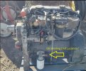
Here is where I seem to keep seeing the oil pressure sensor. On the back of the oil filter adapter there is a plug that I could just remove and screw in the sensor but Perkins says it should be on the block.

Oil Sending Unit Location.jpg

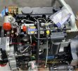
Here are the two temperature sensors I was talking about but one just has a wire from the injection pump with the other hookup having nothing just like this picture. The other sensor has two wires but they are the wrong colors for the temperature gauge, the wires don't affect the gauge and I don't see anything in the schematic to explain where they go or what their function is. The schematic only shows one temp sensor for the gauge which we are both missing.

Sensors.jpg


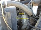
Also, My heater hoses are not hooked up and I have no place to do so. From what I can find, is this typical location???


Heater Hoses Location.jpg


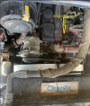
Last, I have a disconnected Green heavy gauge wire that is fused and then turns to red after the inline fuse. I FINALLY found a picture of it on line but I can't see what it is hooked to in this angle. If you or someone could let me know and/or take a better picture it would be very helpful.


Green Red Fused Wire.jpg
 

ASV Curious

Member
Joined
Sep 8, 2023
Messages
9
Location
Washougal WA
Had a chance to pop the hood and take a look around my PT100 for you.

Lets start with the oil sender. I looked at your photo and the picture of the engine you have there has the oil filter and starter mount on the intake side of the engine. On mine the filter and starter location are on the exhaust side of the engine. I read that Perkins makes the oil filter mounting location interchangeable to allow the engine to be used in a variety of applications. I looked at both sides of the engine block down low and the oil filter housing. I couldn't find any senders or wires when I looked. I don't think the sender is mounted on the bottom side of the filter mount because I am pretty sure I would have remembered that and I don't see any wire harnesses in that area. The only harness I see on that side is for the alternator and that harness also has the wire that you are looking at in the second picture on the exhaust side of the engine.

Second picture-- brand spanking new Perkins 1104. "What goes here?" What you have circled is the temperature sender. Note that next to it is a bright colored plug. Lets also incorporate the third picture into this as well about the heater hoses. If you look at the heater hose pic you can see the plug on the second picture is where you see the heater hose in the third picture. On my PT100 those locations are swapped. The temp sender is on the outside under the thermostat housing and the heater hose is on the inside by the intake. You want to have them that way because if you don't, you are going to have a bear of a time hooking up your temp sender. You simply can't get tools in there with that heater hose in the way as it is in the picture. The water pump will send coolant out of the head to the heater core regardless of the port its mounted in. Now here is something very important that will save you a ton of time that took me over 2 months to figure out. The temp sender will not thread into the head. You need an adaptor to thread into the head and then thread the temp sender into the adaptor. The threads in the head are British Pipe Thread (BSP)!!! Perkins is a British company after all You will not find an adaptor at your local hardware or auto parts stores because here in the US we use NPT thread and NPT is a different thread pitch than BSP. You can find adaptors on eBay. The Perkins sending units I was experimenting with were M18 thread. The final sending unit I used from that eBay gauge I told you about was 1/8 NPT so I had to get a 1/2 BSP male to 1/8 NPT female converter. A guy from England had them on eBay and I got it from him in about 2 weeks. One more thing on the temp sender-- both the wires on the connector for mine were black. Why they used the same color beats me.

Continuing on the second picture you have "Extra? Wires hooked to it are wrong color for gauge." I saw this wire on my unit when I was working on the alternator and AC compressor. It goes behind the mounting bracket for those units. I had no need to remove my mounting bracket so I don't know what that wire does or what it connects to. Its possible it could be the oil sender. There are oil passages that go into the head and its possible there is a sender behind that bracket that taps into an oil passage. A lot of GM engines (at least those in old cars) have the oil sender on the top of the block above the camshaft so its not unheard of.

On your last picture "What is this wire?" I have the exact same wire and connector going to a thick green wire in the harness. I would place a large wager in Vegas that wire is for the glow plugs. It looks like it needs to move a lot of current with how large it is.


Hope I've given you some good clues for your project.
 

L3akaL3

Member
Joined
Dec 3, 2023
Messages
24
Location
Missouri
I have and verified my black single wire is an oil sender wire. It is black, has power and the oil gauge lights up if I ground it. It is on the passenger side and is part of the same bundle as the injector pump with only those wires in that skinny part of the bundle. I was sore from cutting trees the last few days so didn't go out to work on the skid though to try and hook the sending unit I finally received to the filter housing since I seem to have no other options right now.

Perkins won't help with anything unless I have an engine number and I can't find it anywhere. From what I have read, the geniuses decided to mount it behind the injection pump where it is impossible to see. I have a borescope somewhere but can't find it since it isn't something you use very often so is probably buried in a box somewhere.

Good call on the thick green mystery wire being the glow plugs. I verified that it is a glow plug wire by measuring it and it only gets power when the switch is on preheat. Some more searching and I found that it attaches to the metal strip running across the top of the manifold. If you look at the first picture in my other post, you can see the red part of the wire after the fuse attached to that metal strip providing power to the 4 glow plugs and the wire goes under that "extra stud/nut" at the front. My inline fuse was missing/removed so I don't know what size it is supposed to be so I am going to try a 40 Amp first since the glow plug fuse in the fuse box is a 50 amp. From what I read, each glow plug should pull about 8 amps and it is easier to replace the inline fuse than the one in the fuse box so I'm going to make that one smaller at 40 A than the other 50 A.

As far as the "wrong color" wires on the other sensor I am pretty sure that is another coolant sensor and not an oil sender. I will investigate further when I have time. I only have one oil sender wire and that sensor with the two wrong color wires attached has two connections. I'll try to peel back the protective sheath and find some wire numbers.

As far as schematic inaccuracy, in trying to chase down this stuff, I figured one shortcut would be to eliminate what I know I don't have. Example, I don't have an A/C compressor so I can find and label the wires for that and eliminate them from my search. I also don't have the compressor that drives the reversable fan activation. The schematic doesn't even show the switch, the wires or the mini compressor for that so I guess I will have to trace those with a meter. I have a switch and it has power but just isn't hooked t anything farther down. I would love to know what the compressor looks like and where it is though so I can get a hint of where the wires might be. I took the reversable fan off because one of the blades had a nick in it making it unbalanced so I am just putting on a regular PT100 fan. If I can get the compressor and plumbing sometime in the future then I'll put the other fan back on and fork out the $900 for a new blade.

I need to take a picture tomorrow. I have another mystery. I have a "Hockey puck" looking type thing hanging down underneath near the track on the passenger side. It's just hanging there by two wires, a circular thing about 1-1/2" to 2" in diameter. Almost looks like a sensor or limit switch maybe. Maybe something to do with load leveling? I don't have my skid in the air jacked up or anything so getting under it is bear. If I keep this thing, I am going to have to build some heavy duty ramps or something.
 

ASV Curious

Member
Joined
Sep 8, 2023
Messages
9
Location
Washougal WA
Sounds like you are making progress! I used my PT100 for about 4 hours yesterday making a new trail in my upper 20 acre lot. The machine ran great and the temp never went over 170-- though it was a cool day with 45 degree temps. The trail turned out nice- just need to do the finish work on it and we will be all set.

The oil sender must be under the injection pump somewhere if the wire is on the passenger side. That pump is very large and it definitely blocks the view. Too bad Perkins thought that would be a great place to put an engine number! What were they thinking?

You've got the glow plugs figured out. As for that other sensor in the head I had an idea. The injection pump has that cold running feature and you and I have both found the wire for that but don't know where to hook it up on the injection pump. Something has to tell that wire that its really cold so current will flow to something on the injection pump that changes the injection timing. Maybe that is what that other sensor does in the head?

I don't have any hockey puck type thing. Do you have a load levelling switch on your dash? Mine didn't come with that feature but I saw it on the wiring diagram. Perhaps that puck thing is the sensor for that? It does not sound like its mounted correctly-- anything hanging from wires near the track is going to get ripped off for sure. I think it should be inside the belly pan.

I do have the reversible fan but I don't know if it really works. There is a plastic box behind the operator that has a timer in it from what I have discovered and it was disconnected from power when I got the machine. There was a hot wire coming off the battery so I hooked it up to that with a switch but I can't tell if its working. Those reversible fans were added on as an afterthought I think for the forestry version of the PT100. The compressor mounts above the valve cover and hangs off the vent panel behind the hood. As for what the compressor looks like I can share this. Do you have a truck with a Firestone air bag system? The compressor looks exactly like the compressor Firestone uses for their air bags. Parts for that Cleanfix fan sure are EXPENSIVE. I don't think I would worry about putting it back into service if they want $900 for a stupid fan! That's just ridiculous! Just keep the vents clear with a battery operated blower and you will be fine.
 

L3akaL3

Member
Joined
Dec 3, 2023
Messages
24
Location
Missouri
Just a replacement blade for the fan is $900. The whole fan is over $6,000 and then the compressor, pipes etc are extra on top of that!!!! If I get this thing fully going, I might call some salvage yards and see about getting the missing parts, blades and skid plates and whatever else I find I am missing and then make a road trip to get them. (The shipping on the skid plates would probably be ridiculous)

I went out today and made "some" progress but I am still stuck. I located a very small plug that looked out of place under the injection pump so I put 8mm or maybe a 6mm, I forget now, wrench on it and pulled it out. It was oily on the back and the threads looked like they matched my new oil sending unit so I went for it. Yeah, one thing fixed!!

Started it up and had oil leak from oil filter housing. Mount bolts weren't even tight! LOL Wonder what else is loose? Anyway, fixed that leak.

No coolant leak so now I am scratching my head. I could have sworn there was coolant under it when I put it in the shop. Maybe old stuff from the disconnected heater hoses?

So then I finally found a couple unmarked black wires, one has 7V on it and other is dead ground. Jumper together and miracle of miracles, temperature gauge pegs out. I found the temp wire!!! Problem is it won't reach the "extra wires sensor" so hooked it to the one the cold start solenoid was hooked to on the passenger side. Problem is the temp gauge pegs if I have the ground or the cold start solenoid hooked to the sensor. The hot temp gauge wire just wants to be on the sensor by itself with nothing hooked to the other terminal. I couldn't run it long enough to see if it will read correctly with only one wire or not though. Weird thing is the wire had a fork type terminal on the end like slides under a bolt instead of a blade connector. I cut it off and put the blade style on it. I'm almost tempted to try splicing/extending the wires so they reach the other "Extra wrong color wires" sending unit on the driver's side and see if it would make a difference. I will probably try that tomorrow.

I rewired the alternator per your way. Tach kind of works, it seems to read high to me but it does respond with the white wire on the "W" terminal. My alternator isn't charging however. I tried putting the white wire back on the D terminal and even tried putting the Hot battery wire on the D terminal and gray & white wires on the B like the diagram and still wouldn't charge. Once I get my lift lock and can tilt up the cab and disconnect the battery, I guess I will pull the alternator and take it to a guy here that rebuilds them and have him check it out.

I tried to get to my heater/Air conditioner fans but can't get to them. I pulled the 6-8 allen head bolts that run along the sides of the panel and pulled the filter and control panel but it still won't budge. Those noisy fans are going to drive me nuts but I am going to want heat in the winter.

I think when/if I get this done, I'll do a long thread of everything I have found since there seems to be a lack of information on this model.

Is your Fecon mulcher the horizontal drum type or the rotary like a brush hog mower? I am trying to decide which I should go with. The rotary ones are cheaper and I hear easier and less expensive to maintain. They do better on little stuff like brush etc and will do up to around 6"-8" trees. Down side is I read you can't get down to ground level and throw stuff everywhere. The horizontal drums are expensive, break a lot and expensive to maintain but you can take on just about anything, go below ground to almost create top soil by mixing the mulch with the dirt, take stumps all the way down until they are gone etc.

I mostly will be doing small trees but it would be nice to just grind up all the big stuff that is already down from old ice storms and not leave stumps on the stuff I am taking down.
 

L3akaL3

Member
Joined
Dec 3, 2023
Messages
24
Location
Missouri
Here is my version of updated schematic for PT100 Forestry showing corrected Alternator wiring and also notes where Oil Pressure sending unit is...
 

Attachments

  • PT100 Forestry-Electrical Schematic.pdf
    266.8 KB · Views: 3

L3akaL3

Member
Joined
Dec 3, 2023
Messages
24
Location
Missouri
So I got to thinking about what you said about the cold start and what I had found and got an idea so just went out and verified and I think I have it figured out.

In some pictures, it often shows that the injection pump has a wire going to the temperature sender on the same side of the engine close to it. Like you said, something has to tell it when to use the cold start setting. It occurred to me that when the engine is cold, the sender might work opposite a "normal" temperature sender and be short to ground when cold and then open as the engine warms up. I just went out and ohmed the sending unit and sure enough, it is dead short across the terminals on that one. That is why my temp gauge pegged max when I hooked both wires to it.

I then ohmed the temperature sender on the opposite side of the engine and it is infinite open as it should be when cold. I am going to make an extension to the temperature wires so they reach that one. (It's the one that had the "extra wires that were the wrong color" hooked to it.) This should fix the temp gauge problem. I suspect the wrong color wires connector is probably for my missing air conditioner compressor or something that would be near there.

As for the cold start temp sender, I haven't decided if I am going to mess with it or not. I suspect the other white wire I had that when I grounded it, blew the injection pump fuse probably goes to the other side of the temp sender near the injection pump. The diagram shows the cold start wire sharing the power with the fuel pump and injection pump. I'm thinking the power goes through the temp sender when cold to the wire that goes to the solenoid at the bottom rear of the injection pump to activate the cold start function, then when the engine warms up, the temp sender opens the path and shuts off the cold start function.
 

ASV Curious

Member
Joined
Sep 8, 2023
Messages
9
Location
Washougal WA
At costs like that I would abandon that Cleanfix system. It just isn't worth that kind of money and effort. A good DeWalt battery blower can be had for $100

The correct temp sender location is on the passenger side of the cylinder head above the injection pump. That picture of the new Perkins 1104 where you labeled "What goes here"-- thats the correct temp sender location. That is why your wires don't stretch to the other one-- they are supposed to be hooked to a sender located on the passenger side. As we don't know exactly the purpose of that sender, though we have suspicions it may be for the injection pump, I wouldn't try wiring that to the gauge.

I shared I was unsuccessful in my search to find the correct sending unit for the gauge so I went with an aftermarket sender and gauge and used the factory wiring with it.

Sounds like your alternator isn't working even with the corrected wiring. I removed my alternator without disconnecting the battery. I was just very careful and immediately wrapped electrical tape over the lead to the battery when I disconnected it. You should be just fine. Have you put in that missing Diode yet? The tach works-- Yay! I think my tach connection is a little wonky because a previous owner hooked the gray wire to the W terminal which fed it 12V and that terminal is supposed to send a signal, not receive 12V. When I start my machine the tach needle gets stuck at around 800 RPM but eventually frees itself up and works normally. I'm idling my machine at around 1200 RPM. If I go lower than that the thing starts to vibrate.

I haven't had any problems with my heat and AC fan. One of my fans for the AC condenser had a bunch of broken blades but I found a replacement on eBay for $80-- better than the $225 TLP wanted.

My mulcher is a drum mulcher and it looks positively evil. As I've told many people-- I have the perfect machine for any zombie apocalypse!! The rotary mulchers are cheaper for sure but I don't think they are as effective. Think about it-- you cut a tree or brush off a few inches above the ground what is it going to do? Its going to sprout again and send up a bunch of shoots. That's what the blackberry, alders and maples do around me. If you use the drum mulcher on them it rips them up below the ground and severs the roots as well as mulch up the soil so grass can take hold easy. Its nice knowing once I pass the mulcher thoroughly over an area that I'm not going to get a lot of what I cut down trying to come back. I guess it boils down to does the thoroughness of the drum mulcher with its extra cost and maintenance outweigh the more limited capabilities and lower cost of the rotary mulcher? You will have to be the decision maker on that. If you do go with a drum mulcher as I said before get a domestic one not Chinese. The China stuff is going to break a lot more than a domestic unit.
 

L3akaL3

Member
Joined
Dec 3, 2023
Messages
24
Location
Missouri
It's hard to see but the injection pump cold start solenoid wire goes from the back bottom of the pump to the temp sender on the same side of the engine. It is a factory wire and very short. I guess I have to disagree and do think that the "shorted" temp sender is correct where it is and is so the cold start works only when the engine is cold. I wasn't going to wire it to the gauge, I was going to wire it to the injection pump (it already was) and then add to it the hot wire running on the same feed as the injection pump and fuel pump as it shows in the schematic already tied in on white wire 600-A28A WH-16. Since that temp sender is dead short when cold, the current would pass through to the cold start solenoid on the pump then shut off when the temp sender opens as it warms up.

Now I could put the other temp sensor where the heater hose is on the pictures and run the senders side by side and then put the heater hose on the driver's side. My heater hoses do run down the driver's side anyway so it would be easy to do. Then I would just have to route the other hose around to get to the back of the water pump. I'll probably remove my air conditioner hoses since there is no compressor to hook to so I was going to route the heater hoses where they were to get to the passenger side. If I did this instead, I would only have to reroute one hose instead of both.

This gets me to my current drama. I don't have outlets for the heater hoses. I searched all last night and this morning and have found 3 different potential thread sizes for them. You had said 1/2" BPT when you were putting in your after market temp sender but 1/2 is a standard size matched to a British pipe thread plus they look larger than 1/2"? I found a temp sender description for generic Perkins 1104C-44T that claimed it was M18 x 1.5 thread but then another one that said it was M27. I could remove the plugs and then just compare them but not sure how accurate screwing them into a hardware store/plumbing supplier gauge would be.

Good point about he alternator and I was thinking that myself. Speaking of, I suspect they put too short a belt on the alternator. My adjustment bolt on the sliding adjustment bracket is partially covered by the engine. Therefore, I have to completely remove the alternator to get to the wires, and stuff.

One thing I realized last night is my battery light never comes on. I only realized my alternator wasn't working because I measured the voltage on the posts byt eh engine and it didn't go up when the engine was running. I am wondering if that resistor inside the fuse box is bad. Have you split the fuse box before? It looks like there are 4 tabs on the edge of the box but I don't know if you are supposed to put a screwdriver in there and angle outward, inward, just push down or how it releases.

I couldn't find my borescope so have another one on the way so I can hopefully see the engine number. Maybe I can get the hose outlet specs once I get a number. My Loader lock and new fan are supposed to be delivered today.

I Probably won't work on it today. I'm about to head out and clear cedar trees with the chainsaw and chipper. Oh Joy!!

EDIT - Yes, the diode is in and oil pressure light works as advertised and no hot gauges with ignition off.
 

L3akaL3

Member
Joined
Dec 3, 2023
Messages
24
Location
Missouri
Making progress. If your inside fans for the heater and Air Conditioning ever get loud and vibrate, remove the outside air filter intake to get access to see the inside of the fans like so.....

Air Intake Filter area.jpg


I had mud dauber wasp nests in there causing the fans to be out of balance. Cleaned them out and now everything is whisper quiet.

It looks like the wasps were getting in where the wire bundle goes through an opening at the top back of the cab. This is the view from inside that filter panel.

Wasp Access.jpg

I'm going to cut some foam and stuff it in there to keep them out from now on.


I got the temp sensor wired up and working. I also made a new rear window. The old plexiglass was all scratched up and yellowed.

I got the battery light working and what I hope is the last hydraulic leak tightened and stopped. I think I'm almost done and ready to take it for a test run except for the alternator but will have to wait for Xmas to be over to take it to him.

My cab doesn't want to go all the way back down though after tilting it and I don't see it hitting on anything. There's about a 3/4" gap. Since I owned it, it's never been all the way down and bolted. ( I don't even know where the bolts are. There just holes all around with no bolts or nuts so I will have to figure that out.

That "hockey puck thing" is an electrical connector with a ribbon type wire bundle. I looked around underneath but didn't see anything that matches. It is near the back of the engine so I am not sure if it goes on the engine, the hydraulic pump or some solenoid somewhere. I guess I will clean it up and search for wire numbers or colors. It covered in black goop old hydro fluid and dirt but it was end of the day and I was tired of being under there so called it a night.
 

L3akaL3

Member
Joined
Dec 3, 2023
Messages
24
Location
Missouri
Stupid question. Which way does the cab tilt brace go when you are lowering it back down. I'm talking about the 2" wide tab of metal that hangs from the cab and "Falls into place" to a bracket so the cab stays up should the struts fail. My brace is slightly curved so it can go either above or below the brace it locks in to. When you take it out of the locked position, do you push the cab up a little more then pull it forward towards the front of the machine or should it fall towards the back and fold up in there?
 
Top