• Thank you for visiting HeavyEquipmentForums.com! Our objective is to provide industry professionals a place to gather to exchange questions, answers and ideas. We welcome you to register using the "Register" icon at the top of the page. We'd appreciate any help you can offer in spreading the word of our new site. The more members that join, the bigger resource for all to enjoy. Thank you!

299D No regen

Chrisso

Senior Member
Joined
Apr 6, 2021
Messages
448
Location
Australia
Occupation
Diesel Mechanic
Ok. Are there any more active codes? If not that would confirm for sure you've unplugged the correct sensor.

If you're still getting the same -3 you most likely have a wiring issue.

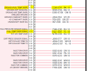
Next step is to turn battery isolator off and remove the plug at the engine ECM that has our two fuel temp sensor wires. There's two 80 pin plugs there. Should be easy to identify as it's the 80 pin plug with the most wires running to it...
1696977567552.png

Leave your little bridging wire in the sensor end. Grab a multimeter and check resistance between pins 23 and 33. Report findings. Wiggle the wiring throughout the engine harness and report if the resistance readings changed.

Then, just for the sake of it, remove your jumper wire from the sensor end and plug that end back into the sensor. Check resistance again from from the same pins 23 & 33 at the engine ECM, but this time gently but firmly wiggle the fuel temp sensor plug. You should not see any change to resistance. If you do you'll need to order and install that plug repair kit I mentioned a few posts ago.

Let us know how you go.
 

Jeffrey Bandel

Senior Member
Joined
Jul 25, 2019
Messages
348
Location
Radford, Virginia
I did a quick test this morning. I get 5 volts to the harness if the I ground my voltmeter to the battery. If I ground it to the black wire on the the harness I get nothing. Sounds like I have a grounding issue in the harness.
 

Chrisso

Senior Member
Joined
Apr 6, 2021
Messages
448
Location
Australia
Occupation
Diesel Mechanic
Sounds like I have a grounding issue in the harness.
Not sure about that. The black C249 wire is basically a signal wire to the ECM. The ECM reads the return voltage on this wire and converts that to a temperature reading, so I'm not sure if your quick check is actually checking anything other than the F421 yellow wire. I could be wrong.

I'm a fan of testing wiring independently from the ECM which is what the test I mentioned above does.

My slots in my ecm for pins 23 and 33 are not yellow and black. They are orange and green.
I'd be double checking your wire numbers stamped into the ECM plug and also make sure you're looking at the correct ECM. If still unsure you can always confirm they are the correct wires by doing continuity tests with your multimeter.
 

Jeffrey Bandel

Senior Member
Joined
Jul 25, 2019
Messages
348
Location
Radford, Virginia
My wiring diagram says they go into ECM J2. It has 80 pins--8 across and 10 down. I can see where 1,8 and 80 are stamped. I've done countless continuity tests on this ecm. I don't know what I am missing.
 

Chrisso

Senior Member
Joined
Apr 6, 2021
Messages
448
Location
Australia
Occupation
Diesel Mechanic
I've got nothing, this is all Kubota. Maybe post a picture of what you're seeing?
 

Chrisso

Senior Member
Joined
Apr 6, 2021
Messages
448
Location
Australia
Occupation
Diesel Mechanic
You've got the rough location of that ECM in your schematic. That ECM should be located behind a panel that requires removing. The ECM itself should have Kubota printed in it somewhere usually. Are you seeing that at least?
 

Jeffrey Bandel

Senior Member
Joined
Jul 25, 2019
Messages
348
Location
Radford, Virginia
Here is a picture of J2. The black multimeter prong is in pin 23 (yellow wire, not black). Red prong is in pin 33 (white wire, not yellow). Am I missing something obvious?
 

Attachments

  • 20231012_132005.jpg
    20231012_132005.jpg
    2.2 MB · Views: 8

Jeffrey Bandel

Senior Member
Joined
Jul 25, 2019
Messages
348
Location
Radford, Virginia
I am at the engine ECM. I do not see anything stamped on it to indicate which port is what. My schematic says it is in J2 E-C1. Is that the rear or front port?
 

Nige

Senior Member
Joined
Jun 22, 2011
Messages
29,426
Location
G..G..G..Granville.........!! Fetch your cloth.
I can never remember which is which. I normally just look for wire numbers and colours.
The pin numbers might be stamped on the inside, which would require you to remove the connectors to find them.

EDIT: As you look at the two connectors on a vertically-mounted ECM like this one, J1 should be on the left, J2 on the right.
 

Jeffrey Bandel

Senior Member
Joined
Jul 25, 2019
Messages
348
Location
Radford, Virginia
I believe I found them. The connector is the most rear one (or the left one when looking at them). On the yellow signal wire on I got good resistance. The black wire has no resistance.
 
Top