• Thank you for visiting HeavyEquipmentForums.com! Our objective is to provide industry professionals a place to gather to exchange questions, answers and ideas. We welcome you to register using the "Register" icon at the top of the page. We'd appreciate any help you can offer in spreading the word of our new site. The more members that join, the bigger resource for all to enjoy. Thank you!

287b new injector pump wont send fuel to the injectors

Kat287b

Active Member
Joined
Dec 7, 2021
Messages
27
Location
Homer, Alaska
Just had my injector pump rebuilt. I get fuel across the pump and out the return line but I cant get any in the injector lines. There is 2 solenoids on the pump, the one on top has 12+ volts with the key on and the one on bottom has nothing. Should the one on the bottom have power at any given time? I assume there is a relay of fuse but I don't have a manual or wiring diagram for this machine.
 

Simon C

Senior Member
Joined
Jul 1, 2015
Messages
686
Location
Rocky Mountain House , AB., Canada
Occupation
Heavy Equipment Mechanic
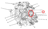
Followed the entire schematic for your machine. Fuel shut down solenoid is Part number #231-2999 .
It is fed by wire A309-EA15 GY-18.
This wire goes through multiple plugs and is fed by Fuse Block 1 , Fuse 18 - 10 Amp
Check that fuse with a test light to make sure it is okay.
Maybe Nige will check out the schematic to make sure I am correct.
Maybe the solenoid is grounding out or the harness is having issues. There is also a ground strap behind the fuel tank ,I believe that could cause problems.
Let us know if fuse is okay.
Simon C
 

Kat287b

Active Member
Joined
Dec 7, 2021
Messages
27
Location
Homer, Alaska
The one on the bottom doesn't show on your diagram. There is power to that one on top with the key on. My pump is a denso 196000-5030 4.
 

Nige

Senior Member
Joined
Jun 22, 2011
Messages
29,914
Location
G..G..G..Granville.........!! Fetch your cloth.
Strange. That illustration above came straight out of the 287B Service Manual for your Serial Number.

The other strange thing is that even the electrical schematic (again for your S/N) does not show a 2nd solenoid.

Can you post a photo of the 2nd solenoid.?
Can you also please identify any wire colours & numbers that are connected to both of the solenoids in your pump. Also does each solenoid have 1 or 2 wires connected to it.?
 
Last edited:

Kat287b

Active Member
Joined
Dec 7, 2021
Messages
27
Location
Homer, Alaska
IMG_2060[1].JPG
Looking down on the Injector pump from above, there are 2 separate wires going to 2 separate solenoids. The green wire on the top is actually spliced via butt joint connector to the red wire and the lower red wire connected to the lower solenoid. Both wires have the same single pin plug in. Only the top wire has power with the key on.
 

Kat287b

Active Member
Joined
Dec 7, 2021
Messages
27
Location
Homer, Alaska
IMG_2058[1].JPG
Here's the lower solenoid. They both are a single stud with nut- you can see the protective boot covering the stud here.
 

Nige

Senior Member
Joined
Jun 22, 2011
Messages
29,914
Location
G..G..G..Granville.........!! Fetch your cloth.
We need an input here from our resident FIP expert, and that's not me.......
Can you post a photo showing the complete Denso reference number on the plate in the top of your photo please.?

OK, so you have a black wire pigtail coming out of the lower solenoid. Does the wire colour change when it gets to the other side of the white connector in the bottom RH of the photo.? if so, what colour goes away from it to the engine wiring harness.?
 

Kat287b

Active Member
Joined
Dec 7, 2021
Messages
27
Location
Homer, Alaska
IMG_2061[1].JPG
Here is the wiring harness, which has 2 separate red wire leads going to the 2 pump solenoids, 1 white wire going to the oil sending sensor and a green wire that is clipped- goes nowhere.
 

Nige

Senior Member
Joined
Jun 22, 2011
Messages
29,914
Location
G..G..G..Granville.........!! Fetch your cloth.
We need an input from @thepumpguysc. He's the man to take this further.
I suspect one will be a shutdown solenoid and the other one a cold start device, designed to energize if the coolant temperautre is below a certain value.

Can you read the number marked on the outside of that red wire.?

Someone has definitely been messing with that electrical setup because those are not Cat wiring harness connectors.
 

Kat287b

Active Member
Joined
Dec 7, 2021
Messages
27
Location
Homer, Alaska
We need an input here from our resident FIP expert, and that's not me.......
Can you post a photo showing the complete Denso reference number on the plate in the top of your photo please.?

OK, so you have a black wire pigtail coming out of the lower solenoid. Does the wire colour change when it gets to the other side of the white connector in the bottom RH of the photo.? if so, what colour goes away from it to the engine wiring harness.?
 

Attachments

  • IMG_2005[1].JPG
    IMG_2005[1].JPG
    2.2 MB · Views: 10

Kat287b

Active Member
Joined
Dec 7, 2021
Messages
27
Location
Homer, Alaska
Followed the entire schematic for your machine. Fuel shut down solenoid is Part number #231-2999 .
It is fed by wire A309-EA15 GY-18.
This wire goes through multiple plugs and is fed by Fuse Block 1 , Fuse 18 - 10 Amp
Check that fuse with a test light to make sure it is okay.
Maybe Nige will check out the schematic to make sure I am correct.
Maybe the solenoid is grounding out or the harness is having issues. There is also a ground strap behind the fuel tank ,I believe that could cause problems.
Let us know if fuse is okay.
Simon C
Fuse 18 on mine is good, it's actually a 15A. I have 5 relays but I can't figure out which one is related to the pump.IMG_2054[1].JPG
We need an input from @thepumpguysc. He's the man to take this further.
I suspect one will be a shutdown solenoid and the other one a cold start device, designed to energize if the coolant temperautre is below a certain value.

Can you read the number marked on the outside of that red wire.?

Someone has definitely been messing with that electrical setup because those are not Cat wiring harness connectors.
 

Kat287b

Active Member
Joined
Dec 7, 2021
Messages
27
Location
Homer, Alaska
The red wire to the top has these numbers- CSA 234608 TEW. The red wire to the lower has none that are readable.

Even if someone has been messing with these wires, remember that this thing pumped fuel before I had it rebuilt. The reason I had it rebuilt is that my crank was getting a lot of fuel put into it, so I suspected the main two way lip seal on the injector pump shaft had to be it. The pump was rebuilt with new solenoids and tested before he sent it back to me. I just cant get it to send fuel to the injectors, so I think it has to be the FSS isn't allowing that. The question is, is there supposed to be power to that lower solenoid? Or does that even serve a function as far as sending fuel to the injectors?

Is there any other reason that the pump wouldn't push fuel other than the FSS isn't working? I know there is fuel in the pump as when the electric transfer pump is activated, when I crack the return line bolt I get a good flow of fuel.
 

Nige

Senior Member
Joined
Jun 22, 2011
Messages
29,914
Location
G..G..G..Granville.........!! Fetch your cloth.
The question is, is there supposed to be power to that lower solenoid? Or does that even serve a function as far as sending fuel to the injectors?
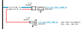
Check out the electrical schematic that I sent to you, Page 13, Grid G-10.
The cold start device is shown as per the snip below. A temp switch with incoming Ignition-controlled power to it on wire 110-GN that when it closes energizes what is labelled as the "cold start Pump As" via wire G455-PK.

1704144349972.png

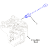
The cold start switch #2 is located on the end of the cylinder head as shown. I am assuming that it will be on the end of the head closest to the FIP location. It should have a 2-pin connector on it.

IMHO (and unless I'm missing something) you still ought to get smoke from the chimney when cranking even if the cold start device was not working.

1704144409912.png
 

Kat287b

Active Member
Joined
Dec 7, 2021
Messages
27
Location
Homer, Alaska
Ok, so what would be the cause of the pump not sending fuel to the injector lines? The solenoid has power with the key on, and the electric fuel pump is running fuel thru the intake and out the return on the Injector pump.
 

Kat287b

Active Member
Joined
Dec 7, 2021
Messages
27
Location
Homer, Alaska
Check out the electrical schematic that I sent to you, Page 13, Grid G-10.
The cold start device is shown as per the snip below. A temp switch with incoming Ignition-controlled power to it on wire 110-GN that when it closes energizes what is labelled as the "cold start Pump As" via wire G455-PK.

View attachment 302033

The cold start switch #2 is located on the end of the cylinder head as shown. I am assuming that it will be on the end of the head closest to the FIP location. It should have a 2-pin connector on it.

IMHO (and unless I'm missing something) you still ought to get smoke from the chimney when cranking even if the cold start device was not working.

View attachment 302034
The cold start is there and has power to it but is that not independent of actuating fuel flow? It should crank and feed fuel even if the cold start isn't working.
 

Kat287b

Active Member
Joined
Dec 7, 2021
Messages
27
Location
Homer, Alaska
I put the gear on, he had inserted a new key and it was already tapped into the shaft snugly- it is definately in there.
 
Top