• Thank you for visiting HeavyEquipmentForums.com! Our objective is to provide industry professionals a place to gather to exchange questions, answers and ideas. We welcome you to register using the "Register" icon at the top of the page. We'd appreciate any help you can offer in spreading the word of our new site. The more members that join, the bigger resource for all to enjoy. Thank you!

1985 JLG 40H restoration time

J_Lin

Member
Joined
Oct 26, 2013
Messages
16
Location
Saskatchewan, Canada
Occupation
Self employed
Hi all! My acquired '85 0r '86 JLG 40H is gonna get some TLC. sn// 0308509376

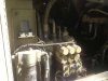
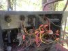
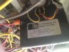
I've attached some pics showing what I believe are Racine valves and some excellent hay-wiring that should win some awards. I have the maintenance manual 3120240 as well as the parts manual.

PQ controllers disabled and toggles installed for everything. Although the machine is operational (and old) I still feel that it is worth spending the time and money to restore proper function. Figure 4-4 of the manual shows the platform box (three PQ controllers) and figure 2-46 shows the ground control panel.

I haven't used the machine extensively because with the toggle switch controlling the drive forward and reverse my concern was that the brakes were not being disabled and I did not want to damage anything more than it has been.

I have the JLG wiring schematics and i have to say they do not help much compared to some of the Snorkel diagrams I have used in the past.

Am I able to find diagrams that would help me to figure out and restore the PQ controller harness'. Its a monkey's lunch I know, and I may have to purchase new controllers. I am also aware of the condition of the boom harness etc. Thanks.
 

Attachments

  • IMG_2119-2000.jpg
    IMG_2119-2000.jpg
    36.9 KB · Views: 333
  • IMG_2118-2000.jpg
    IMG_2118-2000.jpg
    51.2 KB · Views: 325
  • IMG_2117-2000.jpg
    IMG_2117-2000.jpg
    37.5 KB · Views: 296

J_Lin

Member
Joined
Oct 26, 2013
Messages
16
Location
Saskatchewan, Canada
Occupation
Self employed
Had some success! I had ordered the PQ tech supplement a while back and it finally arrived in the mail. This gives me the color codes for the operational wires out of the controller. Although the wiring is all still in the platform control box (what a mess!) the process of chasing what works with what valve is a work in progress.

Drive for example, is connected to a toggle with a power wire and the forward/reverse wires. My question is what additional harness wires are needed to connect to the controller and to the valve to restore PQ function. I'm assuming the controllers are no good at this point but this is where I am right now. This is where the JLG wiring diagram gets very confusing.

I know this seems a little ambitious but I've been here before with this stuff. Chasing harness wires, continuity testing etc. is all par for the course and I have no doubt there will be harness issues as there is always a reason as to why stuff gets bypassed in the first place. I'm assuming all the harness will be pulled apart at some point and its gonna get messy for a bit.
 

OFF

Senior Member
Joined
Sep 30, 2009
Messages
1,048
Location
Alberta, Canada
Occupation
HD Mechanic
wow, that is a mess alright! I haven't seen one that badly butchered before. The 40HA stuff won't do you much good I'm afraid. They are an articulating boom. A lot of the 40HA's were all toggle switches and only 1 controller (for drive) that was connected directly to the hydraulic pump.

60H stuff might work for you. I have ton of it as well.
 

J_Lin

Member
Joined
Oct 26, 2013
Messages
16
Location
Saskatchewan, Canada
Occupation
Self employed
Hello! Thanks for your reply! I've got some time this morning and have been scanning through the older thread. There is so much info here and it is surprising how many old machines still in operation. I've got three PQ's and a manual steering valve. Ironically I worked with the mechanic that hay-wired this machine a few years back. His philosophy was simply to get it back in operation for the construction crew. I bought the machine last year after it had been sold privately about ten years ago from the construction company. The mechanic is a great all round guy and was simply told to NOT spend money. I can relate to that. That type of repair wouldn't work nowadays tho in respect for the crew that uses the machinery. But I've seen this stuff before so I'm not scared (ya right).

Its tough to read the JLG diagrams, very confusing. I'm not sure yet how the brakes are released on this machine, but if the 60H is a bigger version of the 40H, there may be a chance. I'm not sure what damage has been done with the toggle switch installations but that's another part of this. All functions are working, except it seems the swing brake isn't applying as there is turret movement to a degree that makes basket work uncomfortable. May I ask for the 60H information?
 

J_Lin

Member
Joined
Oct 26, 2013
Messages
16
Location
Saskatchewan, Canada
Occupation
Self employed
A few back I was talking with a snorkel tech regarding the ATB50 that I was correcting some hacked wiring amongst other issues. I was instructed to replace the high country drive card with an OEM that was shipped to the shop. In the meantime to move the machine I jumpered the coils in order to move the machine from the yard into the shop. I was cautioned against this by the tech as he told me he wasn't sure what the damage to the coils may result.

This 40H has had the PQ controllers disabled and connected with toggles. I read in this forum that the proportional coils cannot be run this way. Am I going to be faced with failed coils because of this direct wiring?

Also, according to the PQ controller schematic the power to the dump valve is applied once the controller is moved. The toggle switches have a power wire and the reverse forward wires attached. I cannot figure at this point how the dump valve is operated. I've begun reversing the rats nest in the upper control box and do not see how this has been achieved. I should mention that when the foot pedal is depressed the engine experiences a slight load. Maybe the dump has been tied into the foot pedal?

What a mess!
 

OFF

Senior Member
Joined
Sep 30, 2009
Messages
1,048
Location
Alberta, Canada
Occupation
HD Mechanic
Also, is it possible from the pic I posted to determine if indeed these are Racine valves?

Yes, those are Racine proportional valves in the picture. What part of Saskatchewan are you in? Very likely the basket is activating the dump valves using the foot pedal. I don't think that generation of PQ controllers had anyway of activating the dump valves. They were only capable of turning on power to the controller itself.
The coils can be checked with a common ohm meter once they have been disconnected from the circuit. I believe you are looking for approx 60 ohms resistance on a good coil.
 

J_Lin

Member
Joined
Oct 26, 2013
Messages
16
Location
Saskatchewan, Canada
Occupation
Self employed
Ok I finally got some time today and pulled one of the controllers to do some testing. The potentiometer definitely had a couple of dead spots but not surprised. This would cause erratic behavior and is sending me in a direction as to why they were disabled in the first place. I'm gonna have to find a couple of these and replace them and then see if the rest of the controller functions. I've attached the controller wiring and I believe it tells me what you were saying regarding the dump valve. This is making better sense now. I don't think chasing these wires out is going to be too bad, and it will make cleaning up the rats nest easier. This is more straight forward than I first thought. I will know more after testing the harness. Its cracked up a bit, and I may be in a situation where I will be replaced, as well as the hydraulic lines along the boom. This weekend I'll get after testing the coils.

I'm in southern sask. about an hours drive from Regina going east out on an RM acreage. Water's low this year as long as the rains keep away.

You had said that you had 60H stuff? Do you have 60H hydraulic schematics? I'm just wondering how close it would be to the 40. IMG_2125.jpg
 

OFF

Senior Member
Joined
Sep 30, 2009
Messages
1,048
Location
Alberta, Canada
Occupation
HD Mechanic
You had said that you had 60H stuff? Do you have 60H hydraulic schematics? I'm just wondering how close it would be to the 40. View attachment 135936

When you bought a JLG new back in the day, you used to get a package of large drawings specific to that serial number machine. Sort of an "as built" rather than generic drawings. I've got 2 set of those for the 60H, one early set with Racine valve and a later set using Vickers valves. I looked through them a week or more ago, and didn't find anything I thought would be useful to you. But, at the time I was looking for a good electrical schematic, not hydraulic. I'll look again when I get back to work on Monday. Hopefully there will be something you can use.
 

J_Lin

Member
Joined
Oct 26, 2013
Messages
16
Location
Saskatchewan, Canada
Occupation
Self employed
When you bought a JLG new back in the day, you used to get a package of large drawings specific to that serial number machine. Sort of an "as built" rather than generic drawings. I've got 2 set of those for the 60H, one early set with Racine valve and a later set using Vickers valves. I looked through them a week or more ago, and didn't find anything I thought would be useful to you. But, at the time I was looking for a good electrical schematic, not hydraulic. I'll look again when I get back to work on Monday. Hopefully there will be something you can use.


This is starting to make sense to me now, as I find it really difficult to follow the generic electrical schematics. The schematic Snorkel provided me with was outstanding. The construction company architect (at the time) fed the pdf file into his plotter and gave me a very large diagram with stunning clarity and that was the push I needed to get that machine fixed.
 

J_Lin

Member
Joined
Oct 26, 2013
Messages
16
Location
Saskatchewan, Canada
Occupation
Self employed
I pulled the other two controllers to test the potentiometers and I've got three controllers with dead spots and/or low ohms all over the map - I'm going to obtain some new ones and solder them in and then restore the wiring based on the PQ supplement book schematic. Hopefully the pwm converters are still healthy that would be a bonus!
 

J_Lin

Member
Joined
Oct 26, 2013
Messages
16
Location
Saskatchewan, Canada
Occupation
Self employed
Has anybody performed a turret bearing wear tolerance measurement such as described in the 40H service manual? The spec called for is max 0.057" - I did the measuring and found a definite .090". This machine clock says 3500 hrs. The spec also says to replace the bearing if over the 0.057"

I've read whats involved regarding the bearing replacement and it is not surprisingly a major major. Is there any experience out there that could be shared regarding this bearing replacement?

This machine will never be used at its max limits. I am just thinking about the bearing movement could cause trouble with the mounting hardware over time. I know if i ever sell the machine that these issues will have to be disclosed.
 
Top