Papa Goose
Well-Known Member
If you're having trouble with your gauges, here's a quick how-to on rebuilding the electronic instruments (i.e., fuel, ammeter, and H2O temp).
Probably the most common failure on the fuel and H2O is to lose a connection, of which there are three: 12V, signal, and ground. Yes, I konw there are only two connections on the back of each instrument - ground has to connect through the case, which can be the source of many problems.
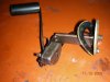
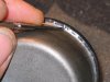
To check the operation of the gauge on the bench, supply 12V, ground the case, and put about a 1K variable resistor (pot) from the signal input to ground. As you're looking at the back of the gauge, 12V is on the right and the sensor input is on the left. Turning the pot should give you full control over the position of the indicator needle. If the needle doesn't move, you'll probably have to open the case (more on this later). The the needle moves on the bench, but not in the tractor, check to make sure the case is being properly grounded - there is a spring tab on the U-bracket that holds the gauge in place (see picture #1 below), which needs to be shiny where it touches the case. If yours looks as bad as the one in the photo, you can bet it isn't grounding the case.
If grounding the case still doesn't fix the problem, check the wire coming from your sensor - it should read some finite resistance to ground, and the resistance should change as the input quantity changes (e.g., fuel level). If your wiring is OK, then you'll have to go after the sensor. Repairing the fuel level sensor is quite possible, but the engine temp sensor is probably not worth trying to fix - possible, but probably more work than it's worth. I can add some more info on this later if anyone is interested.
If none of these things fixes your problem, you'll have to go inside the gauge, which is not as hard as you might think, but it does take some patience and careful work.
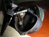
First, leave the last two nuts on the two long screws coming out the back. You can't get it apart by taking these off, and you'll have loose parts inside if you do. You have to peel back the lip of the cover with a small screwdriver - see picture #2. This takes a long time and must be done very carefully - you want to peel it a little at a time without tearing the metal, since you're going to have to bend it back over when you reassemble the gauge.
Once the front cover is off, you can take off the glass and the inside panel that has the label on it. My inside panels were in bad shape, so I sandblasted them, painted them, and made new labels. Yes, it was a lot of work, but they look like new now!
Now you can remove the two nuts on the back, after which the insides will come free from the case. Look closely at the fiber washers, rubber seals, and cupped plastic washers as you remove them - they MUST go back in the same way they came out, or you may have a potential leak, or worse, an electrical short! You might want to make a sketch. Note that the rubber seals and plastic washers go one way - they're not reversible.
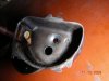
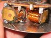
First, take a look at the wiring (see picture #3) - there should be two fine wires connected to the first terminal, and one to each of the other two. The one with two wires is the 12V input, the one in the middle is ground, and the one on the right is the sensor input. If your previous bench test didn't get the needle moving, you can connect directly to the solder tabs and try it again. If you're able to get the needle to move now, that's a very good sign - your problem is a bad connection, which we will address below. If the needle still doesn't move, you may have a bad coil, which likely means the end of your instrument. However, before you give up, check that the needle is able to move freely - if not, you can apply some very thin oil (clock oil is best, but 3in1 will probably work) to the pivot points. Don't disturb the tiny screw on the back, unless you have experience with clock mechanisms - it has to be adjusted properly or your gauge won't work - that's why it has paint on it.
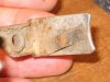
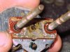
If your needle moves when you connect directly to the solder tabs, the problem is either with the ground connection or the brass screws - we'll fix both. The ground connection goes through the brass plate on the back (between the brass screws), and it may look as bad as picture #4. Brasso is the best way to clean this up, but you can probably also use a scotchbrite pad. Also take a look at the inside of the case where this plate contacts it - it's probably just as bad. I sandblasted mine, but sandpaper or scotchbrite works too.
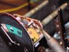
Next we'll take a look at where the long screws make connections internally to the coil wires through ring terminals. This is a major trouble spot, since the screws are likely to corrode and lose the connection with the ring terminal. Fortunately, the screws are brass, so they will take solder if you get them hot enough. Clean a small area with a sharp knife or dremel so the solder has good metal to bond with. Picture #5 shows the soldering process. Use rosin core electrical solder, not solid pipe solder, and NEVER use any kind of flux that you would use to sweat pipes! If you're having trouble getting the solder to flow, first make sure that the place you're soldering is perfectly clean, and then be patient - it takes quite a while to get the brass screw hot enough for the solder to flow. After the solder begins to bond with the screw, slide your soldering pencil over to the ring terminal, which is tinned copper and will take solder very easily. Make sure you have a good solid solder connection between the two - a little extra solder here is OK.
If you're still with me - Congratulations! You're about done with the repair and are ready for reassembly. Put the mechanism in the case first, noting the position and orientation of the fiber washer, rubber seal, and plastic washer. Put the fiber washers on first, then slide the instrument into the case, making sure that the fiber washers are seated in the middle of the holes in the case - they MUST insulate the screws from the metal case, or this is going to be a very short ride. Now, holding the instrument and the case at the same time, slide the rubber seals over the screws, add the plastic washers (cupped side toward the seals) and spin the nuts on. I can't over-emphasize that this must be done carefully - if you get something out of position, it's quite easy to have one or both screws shorted to the case.
After the mechanism is in place, check it one last time with your bench power supply and pot to be sure everything is working before you put the front cover back on - trust me, you don't want to have to take the cover off again! I used a very thin layer of RTV silicon on the rubber seals, just to make sure it doesn't leak (one of my gauges had water in it). Then, I carefully worked the metal rim of the front cover back over the lip of the case. There's probably a much better way to do this, short of using a rolling mill with the correct die (which is how they're made), but a small box end wrench works if you're patient. Make sure to hold the case and cover tightly together while you're rolling the edge, and check the face every once in a while to make sure everything is still lined up - if the cover rotates, it can shift the inside label plate.
Once the cover is completely rolled back over the case lip, you're done!
PG
Probably the most common failure on the fuel and H2O is to lose a connection, of which there are three: 12V, signal, and ground. Yes, I konw there are only two connections on the back of each instrument - ground has to connect through the case, which can be the source of many problems.
To check the operation of the gauge on the bench, supply 12V, ground the case, and put about a 1K variable resistor (pot) from the signal input to ground. As you're looking at the back of the gauge, 12V is on the right and the sensor input is on the left. Turning the pot should give you full control over the position of the indicator needle. If the needle doesn't move, you'll probably have to open the case (more on this later). The the needle moves on the bench, but not in the tractor, check to make sure the case is being properly grounded - there is a spring tab on the U-bracket that holds the gauge in place (see picture #1 below), which needs to be shiny where it touches the case. If yours looks as bad as the one in the photo, you can bet it isn't grounding the case.
If grounding the case still doesn't fix the problem, check the wire coming from your sensor - it should read some finite resistance to ground, and the resistance should change as the input quantity changes (e.g., fuel level). If your wiring is OK, then you'll have to go after the sensor. Repairing the fuel level sensor is quite possible, but the engine temp sensor is probably not worth trying to fix - possible, but probably more work than it's worth. I can add some more info on this later if anyone is interested.
If none of these things fixes your problem, you'll have to go inside the gauge, which is not as hard as you might think, but it does take some patience and careful work.
First, leave the last two nuts on the two long screws coming out the back. You can't get it apart by taking these off, and you'll have loose parts inside if you do. You have to peel back the lip of the cover with a small screwdriver - see picture #2. This takes a long time and must be done very carefully - you want to peel it a little at a time without tearing the metal, since you're going to have to bend it back over when you reassemble the gauge.
Once the front cover is off, you can take off the glass and the inside panel that has the label on it. My inside panels were in bad shape, so I sandblasted them, painted them, and made new labels. Yes, it was a lot of work, but they look like new now!
Now you can remove the two nuts on the back, after which the insides will come free from the case. Look closely at the fiber washers, rubber seals, and cupped plastic washers as you remove them - they MUST go back in the same way they came out, or you may have a potential leak, or worse, an electrical short! You might want to make a sketch. Note that the rubber seals and plastic washers go one way - they're not reversible.
First, take a look at the wiring (see picture #3) - there should be two fine wires connected to the first terminal, and one to each of the other two. The one with two wires is the 12V input, the one in the middle is ground, and the one on the right is the sensor input. If your previous bench test didn't get the needle moving, you can connect directly to the solder tabs and try it again. If you're able to get the needle to move now, that's a very good sign - your problem is a bad connection, which we will address below. If the needle still doesn't move, you may have a bad coil, which likely means the end of your instrument. However, before you give up, check that the needle is able to move freely - if not, you can apply some very thin oil (clock oil is best, but 3in1 will probably work) to the pivot points. Don't disturb the tiny screw on the back, unless you have experience with clock mechanisms - it has to be adjusted properly or your gauge won't work - that's why it has paint on it.
If your needle moves when you connect directly to the solder tabs, the problem is either with the ground connection or the brass screws - we'll fix both. The ground connection goes through the brass plate on the back (between the brass screws), and it may look as bad as picture #4. Brasso is the best way to clean this up, but you can probably also use a scotchbrite pad. Also take a look at the inside of the case where this plate contacts it - it's probably just as bad. I sandblasted mine, but sandpaper or scotchbrite works too.
Next we'll take a look at where the long screws make connections internally to the coil wires through ring terminals. This is a major trouble spot, since the screws are likely to corrode and lose the connection with the ring terminal. Fortunately, the screws are brass, so they will take solder if you get them hot enough. Clean a small area with a sharp knife or dremel so the solder has good metal to bond with. Picture #5 shows the soldering process. Use rosin core electrical solder, not solid pipe solder, and NEVER use any kind of flux that you would use to sweat pipes! If you're having trouble getting the solder to flow, first make sure that the place you're soldering is perfectly clean, and then be patient - it takes quite a while to get the brass screw hot enough for the solder to flow. After the solder begins to bond with the screw, slide your soldering pencil over to the ring terminal, which is tinned copper and will take solder very easily. Make sure you have a good solid solder connection between the two - a little extra solder here is OK.
If you're still with me - Congratulations! You're about done with the repair and are ready for reassembly. Put the mechanism in the case first, noting the position and orientation of the fiber washer, rubber seal, and plastic washer. Put the fiber washers on first, then slide the instrument into the case, making sure that the fiber washers are seated in the middle of the holes in the case - they MUST insulate the screws from the metal case, or this is going to be a very short ride. Now, holding the instrument and the case at the same time, slide the rubber seals over the screws, add the plastic washers (cupped side toward the seals) and spin the nuts on. I can't over-emphasize that this must be done carefully - if you get something out of position, it's quite easy to have one or both screws shorted to the case.
After the mechanism is in place, check it one last time with your bench power supply and pot to be sure everything is working before you put the front cover back on - trust me, you don't want to have to take the cover off again! I used a very thin layer of RTV silicon on the rubber seals, just to make sure it doesn't leak (one of my gauges had water in it). Then, I carefully worked the metal rim of the front cover back over the lip of the case. There's probably a much better way to do this, short of using a rolling mill with the correct die (which is how they're made), but a small box end wrench works if you're patient. Make sure to hold the case and cover tightly together while you're rolling the edge, and check the face every once in a while to make sure everything is still lined up - if the cover rotates, it can shift the inside label plate.
Once the cover is completely rolled back over the case lip, you're done!
PG
Attachments
Last edited: