• Thank you for visiting HeavyEquipmentForums.com! Our objective is to provide industry professionals a place to gather to exchange questions, answers and ideas. We welcome you to register using the "Register" icon at the top of the page. We'd appreciate any help you can offer in spreading the word of our new site. The more members that join, the bigger resource for all to enjoy. Thank you!

John Deere 2154D (hitachi -3 zx250 size with Deere engine) stalling engine when operating hydraulics at low rpm.

Joined
Oct 2, 2022
Messages
6
Location
New Zealand
Hello all, as above when operating this machine at low idle rpm like a warm up scenario, if anything more than 1/4 or half movement of the joystick booming up or arm out it will pull the engine down and if not feathering the controls back toward neutral it will stall the engine. i have diagnosed down to the point where i believe either the MCX controller is not functioning correctly or the MCX controller is not recieving 1 or more of the required sensor signals it needs to operate the torque control solenoid valve and destroke the pumps when a drop in engine rpm is detected. From what i read the torque control solenoid recieves a decrease in voltage from the MCX controller when a drop in engine rpm is detected.
I have measured the voltage at solenoid while pulling engine down close to stall and there is a constant 24v which does not fluctuate.
I can disconnect this solenoid and the problem is solved but then the pump remains at min displacement and movement is very slow.
All pressures and speeds are visible through the monitor so i dont suspect a sensor issue, but i am no expert so asking the question.

Has anybody had and or solved similar problems on deere or hitachi excavators??

Thanks.
 

mg2361

Senior Member
Joined
Jul 5, 2016
Messages
5,163
Location
Pennsylvania
Occupation
Equipment Mechanic
Please post the entire machine serial number.

I have measured the voltage at solenoid while pulling engine down close to stall and there is a constant 24v which does not fluctuate.
It is a pulse width modified circuit. Instead of voltage, try measuring duty cycle. Does that change with varying engine loads?

Does the unit work OK at high rpm? Engine speed sensing circuit being checked thoroughly?

Hopefully someone with more forestry equipment experience will chime in.
 

C9021

Member
Joined
Mar 14, 2024
Messages
7
Location
Europe
Occupation
Business
Common multimeters only measure average voltage so when the voltage stays constant it implies that there are no pulses present or they are at fixed level. So it will give a ballpark, but oscilloscope should be used to be sure just as mg2361 said.
 
Joined
Oct 2, 2022
Messages
6
Location
New Zealand
Thank you all for the replys so far. 1FF2154DTB0210319 is the serial. At high RPM the engine is still pulled down a little more than it should but not to stall point. I have Service advisor and have run several engine tests viewing all the ECU parameters (the only controller i can see through SA) and cannot really fault the engine other than it is old and a bit rough. As i said above all sensors i can see via SA or through the in cab monitor appear to be reading correctly.
I do not have an oscilloscope but will try with my multimeter in the next few days when i return to the machine. I am tyring to get hold of an MPdr cable or cable schematic to build my own to see if i can monitor the MCX inputs/outputs with that. Does anybody know if thats possible?
 

Bullitt

Active Member
Joined
Oct 30, 2022
Messages
35
Location
Central PA
Occupation
Manitou / Gehl & Yanmar Tech, Rental Monkey
Did you see the tm10322 -> Hydraulic system -> tests -> torque control solenoid valve test and adjustment? It does say that a laptop is required but doesn't specifically reference MPDr. I am assuming that is what is used though. I have used my MPDr cable on -3 Hitachi and G John Deere successfully and connected to the machine controllers.
 

mg2361

Senior Member
Joined
Jul 5, 2016
Messages
5,163
Location
Pennsylvania
Occupation
Equipment Mechanic
have run several engine tests viewing all the ECU parameters (the only controller i can see through SA)
While Service Advisor is not ideal for reading machine parameters from the machine controller, it should still be able to communicate with it and you should be able to see the machine sensors with it. If the MCX is not visible in SA, either it is offline (blown fuse, no power or ground, bad MCX), or there is an issue with the CAN network. It would be nice to confirm that one step further with MPDr.
 

LACHAU

Senior Member
Joined
Aug 11, 2009
Messages
995
Location
Saigon, Vietnam
While Service Advisor is not ideal for reading machine parameters from the machine controller, it should still be able to communicate with it and you should be able to see the machine sensors with it. If the MCX is not visible in SA, either it is offline (blown fuse, no power or ground, bad MCX), or there is an issue with the CAN network. It would be nice to confirm that one step further with MPDr.
@mg2361
I don't think the JD2154D is equivalent to the ZX250-3.
I think JD2154D is similar to ZX250LC-1, is that correct?

@BlackSmokeandMetal
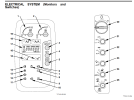
Could you take some photos of JD2154D's gauge cluster let me see.
Does it look like the attached image?

ZX250-1.png
 
Last edited:

LACHAU

Senior Member
Joined
Aug 11, 2009
Messages
995
Location
Saigon, Vietnam
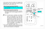
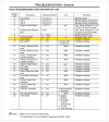
1/- Check to see if the machine reports any errors.
2/- Temporarily adjust the P-Q control parameters of the regulator (Torque Adjustment).
Note: Turn the adjusting screws (8 & 10) counterclockwise little by little while checking the machine's operation.

ZX-1 Diag.png
ZX-1 Diag 2.png
ZX250-1 REGULATOR ADJUSTMENT.png
 
Joined
Oct 2, 2022
Messages
6
Location
New Zealand
1/- Check to see if the machine reports any errors.
2/- Temporarily adjust the P-Q control parameters of the regulator (Torque Adjustment).
Note: Turn the adjusting screws (8 & 10) counterclockwise little by little while checking the machine's operation.

View attachment 308179
View attachment 308178
View attachment 308177
Thank you for this. Yes the monitor displayed is correct. I am not sure what Hitachi it crosses to but chose ZX250 as some parts cross over. I have checked for any faults through monitor and there is none present.
I thought i checked the regulators correctly by checking minimum and maximum pump flows via track time checks but will try back them off a little as you have suggested.
Correct me if i am wrong but the "A" adjustment is how long a pump will flow at max before destroking? And the "B" adjustment is how quickly it will decrease?.?
 

LACHAU

Senior Member
Joined
Aug 11, 2009
Messages
995
Location
Saigon, Vietnam
Thank you for this. Yes the monitor displayed is correct. I am not sure what Hitachi it crosses to but chose ZX250 as some parts cross over. I have checked for any faults through monitor and there is none present.
I thought i checked the regulators correctly by checking minimum and maximum pump flows via track time checks but will try back them off a little as you have suggested.
Correct me if i am wrong but the "A" adjustment is how long a pump will flow at max before destroking? And the "B" adjustment is how quickly it will decrease?.?
In a way of thinking, you are right.
"A" adjustment is how long a pump will flow at max before de-stroke. And the "B" adjustment is how quickly it will decrease.

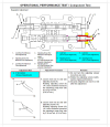
I want to draw your attention to the control principle of the machine called "speed-sensing control".
A malfunction of any part of this "speed-sensing control system will cause the engine to overload.
So I recommend to you:
1/- Check the engine control dial and N sensor again.
2/- Try re-adjusting the torque control solenoid valve.

ZX250 Speed Sensing.png
ZX250 P-Q.png
ZX250 Solenoid Adjust.png
 
Joined
Oct 2, 2022
Messages
6
Location
New Zealand
Hello again, thank you all for your help so far. i was at this machine and attempted to measure the PWM signal to the torque control solenoid backprobing it with frequency measurement on my multimeter. unfortunately this problem has now turned 180Deg and my pumps are now stuck at minimum displacement as if i now have zero signal from MCX. after this i capped the torque control port at rear of P2 regulator and the jumper pipe across to P1 reg and brought the pumps back to full displacement for testing purpose. With the lines plugged I can see the pulse decrease as engine pulls down from approx 160Hz to 130-120Hz, so swapped the P2 flow rate control valve with the torque control solenoid valve causing no change. I have ordered myself MPDr tool but it is not due to arrive for another week and understandably, the customer would rather the pumps at full stroke and still usable at full engine rpm than stuck at min.

From what i think i understand about the regulator operation, i may be able to leave the torque control pipes capped and the regs will still operate mechanicallywithout risking further problems? Can anyone second this this idea or talk me out of it??
 

LACHAU

Senior Member
Joined
Aug 11, 2009
Messages
995
Location
Saigon, Vietnam
Hello again, thank you all for your help so far. i was at this machine and attempted to measure the PWM signal to the torque control solenoid backprobing it with frequency measurement on my multimeter. unfortunately this problem has now turned 180Deg and my pumps are now stuck at minimum displacement as if i now have zero signal from MCX. after this i capped the torque control port at rear of P2 regulator and the jumper pipe across to P1 reg and brought the pumps back to full displacement for testing purpose. With the lines plugged I can see the pulse decrease as engine pulls down from approx 160Hz to 130-120Hz, so swapped the P2 flow rate control valve with the torque control solenoid valve causing no change. I have ordered myself MPDr tool but it is not due to arrive for another week and understandably, the customer would rather the pumps at full stroke and still usable at full engine rpm than stuck at min.

From what i think i understand about the regulator operation, i may be able to leave the torque control pipes capped and the regs will still operate mechanically without risking further problems? Can anyone second this this idea or talk me out of it??
You can completely operate the pump at maximum flow by leaving the torque control pipes capped and the regs will still operate mechanically without risking further problems.
note that you should adjust the regulator as I said in post #11 above.
 
Top