• Thank you for visiting HeavyEquipmentForums.com! Our objective is to provide industry professionals a place to gather to exchange questions, answers and ideas. We welcome you to register using the "Register" icon at the top of the page. We'd appreciate any help you can offer in spreading the word of our new site. The more members that join, the bigger resource for all to enjoy. Thank you!

g188d cam timing

Leeland

Member
Joined
Nov 26, 2017
Messages
19
Location
Madoc Ontario
Hello, I have a dismantled case g188d.(complete rebuild) I really should have marked everything at tdc comp, but I didn’t. Now that I have the cam out, I have noticed only 1 timing mark which I believe is for the pump idler gear. Can someone take a picture of their gear or help me find a way to make my own mark on the gear?
 

Attachments

  • 482EAD9B-43BA-4795-B515-A62C7FB89513.jpeg
    482EAD9B-43BA-4795-B515-A62C7FB89513.jpeg
    969.5 KB · Views: 35
  • 13F54DDB-61A2-4F3F-8539-5E2FD06D5B4F.jpeg
    13F54DDB-61A2-4F3F-8539-5E2FD06D5B4F.jpeg
    1.1 MB · Views: 33

Juskatla

Senior Member
Joined
Dec 12, 2009
Messages
579
Location
Black Creek B.C.
Occupation
Retired
Mines back together long ago, but I remember there being marks to match up for all the gears. Later in the week, I'll be back where I can look at the manual if someone hasn't gotten you the correct info by then.
 

Leeland

Member
Joined
Nov 26, 2017
Messages
19
Location
Madoc Ontario
I have another issue as well. There are several marks on the pump gear. But I guess I would confirm which one is right by looking through the timing window on the pump. I have attached pictures of it too. However the cam is by far my most feared issue.
 

Attachments

  • F45C8B53-FC76-44DB-B7EF-21C68C4A3B66.jpeg
    F45C8B53-FC76-44DB-B7EF-21C68C4A3B66.jpeg
    615.3 KB · Views: 36
  • 2122A61F-6BC3-4E64-ACD4-28C2AF8AAF2D.jpeg
    2122A61F-6BC3-4E64-ACD4-28C2AF8AAF2D.jpeg
    1.3 MB · Views: 34
  • 1D459C54-81B9-4CEE-B096-7C5380B1D2D9.jpeg
    1D459C54-81B9-4CEE-B096-7C5380B1D2D9.jpeg
    690.6 KB · Views: 33
  • 6C071DD1-8D5D-4F5E-A2A3-1DF35E0A9F4C.jpeg
    6C071DD1-8D5D-4F5E-A2A3-1DF35E0A9F4C.jpeg
    1.6 MB · Views: 35

thepumpguysc

Senior Member
Joined
Mar 18, 2010
Messages
7,552
Location
Sunny South Carolina
Occupation
Master Inj.Pump rebuilder
I cant help w/ the cam gear but you are correct on the pump gear.. just look at the side window on the pump & match the lines
 

Leeland

Member
Joined
Nov 26, 2017
Messages
19
Location
Madoc Ontario
Thanks for chiming in. I know you guys are experts on these engines. I simply can’t find any threads on this particular application. At least it’s been a learning experience. I did long hard thinking at one point with a close solution.,

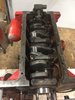
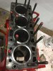
Level the block on the engine stand with a torpedo level.

Throw pushrods in #1, and get the cam at tdc in between exhaust and intake, used the level again (sitting on top of pushrods.

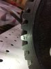
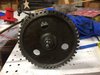
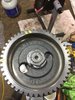
Put the level on the cam gear going vertical. Marked a line on top and bottom of cam gear.

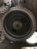
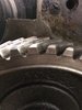
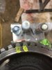
Now throw in the crank at tdc #1 meshing the gears carefully.

Now as long as the dot on the crank lines up with the cam (cam being vertical level with custom lines)and they are both at TDC, I can now spin the crank 360 decrees and be now at TDC Comp Stroke.... right?

I know it’s confusing, but that’s all I got.
 

kshansen

Senior Member
Joined
Mar 11, 2012
Messages
11,173
Location
Central New York, USA
Occupation
Retired Mechanic in Stone Quarry
Looking at that picture it looks to me like something was wearing on the cam gear, just does not look like a factory surface. I'm guessing the timing marks got worn away!

There does appear to be a timing mark on the crank gear in the picture it looks like it's about at 5 o'clock.

I was having a little trouble following your explanation how you were going to do it but after a little time for morning coffee to work it does sound like it should work. As long as you get the valves on their cylinder to be right on "overlap" when piston is at TDC you should be good to go!

And the pumguy should have you all set on the pump timing. I'm thinking there are timing marks on flywheel for the actual pump timing, then again been many years since I worked on an old Case 188
 

Leeland

Member
Joined
Nov 26, 2017
Messages
19
Location
Madoc Ontario
Worn away. Lol ,, so I guess that is why I found a bolt in the pan. I’m surprised the timing cover didn’t have any significant damage. Someone has been in this thing before. (Different cam, and head (yellow paint under orange and gunk), #3 sleeve and piston replaced) The bolt doesn’t seem to have a home though... could be from the timing cover). I might just copy the dots from another used gear, triple check TDC and valve location and give it a go. I dont think it’s a good idea to replace only 1 gear. Might cause premature wear.

The original reason to rebuild was a bad knock. Paid 2500$ for the machine with the extendahoe. Ended up being a badly spun #4 rod bearing. So I’m now going to replace all but the head. I found a decent crank remachined for 500$.

Thanks again for all your help. I didn’t think I would get such quick replies.
 

kshansen

Senior Member
Joined
Mar 11, 2012
Messages
11,173
Location
Central New York, USA
Occupation
Retired Mechanic in Stone Quarry
Well if you have another used gear you should, with some careful measuring, be able to use the relationship between the key way in gear with good marks to determine which teeth on the worn gear would have been marked.

You could also temporarily install the marked gear on the cam and go through the valve over lap method to double check that it works as you would expect then repeat with the worn gear as a double check on the "new" marks you put on it.

Just for kicks install the marked gear one tooth off in each direction to give you a good idea of how much difference one tooth off would make to help you sleep at night!
 

Leeland

Member
Joined
Nov 26, 2017
Messages
19
Location
Madoc Ontario
Thanks for attaching the assembly screen shot. My manual is very vague. I was able to find a small shop locally with a spare cam gear. Very helpful gentlemen that marked the gear for me. I also had him install the top con rod bushings and bore to size, re polish cam journals and install cam bushings in block. I also purchased his spare crank as mine spun a #4 rod bearing. I will attach the pic of new marks.
 

Leeland

Member
Joined
Nov 26, 2017
Messages
19
Location
Madoc Ontario
There was one indent not totally worn off that matched up with the new marks.
 

Attachments

  • 28E5BFEE-3625-4DE4-88B1-67081BF59528.jpeg
    28E5BFEE-3625-4DE4-88B1-67081BF59528.jpeg
    1.2 MB · Views: 22
  • 30EB8385-338A-4D62-9E6F-2E26DE16948A.jpeg
    30EB8385-338A-4D62-9E6F-2E26DE16948A.jpeg
    850.2 KB · Views: 21

Leeland

Member
Joined
Nov 26, 2017
Messages
19
Location
Madoc Ontario
I was just looking at the timing cover and thought of an idea on how the cam gear got so worn. Well I found the culprit. One bolt was too long in the timing cover. I will double check thread depth and possibly regrind to size. Looks like it was a hardware store replacement. As for the bolt in the pan,,, I will keep brainstorming.
 

Leeland

Member
Joined
Nov 26, 2017
Messages
19
Location
Madoc Ontario
Not to many pictures of these engines online, so I will post some progress
 

Attachments

  • 82E306B0-A901-46FC-8947-2607C8F3F94E.jpeg
    82E306B0-A901-46FC-8947-2607C8F3F94E.jpeg
    1.5 MB · Views: 17
  • 5C32F119-01AC-4514-85DB-A8AE4EA0A15C.jpeg
    5C32F119-01AC-4514-85DB-A8AE4EA0A15C.jpeg
    1 MB · Views: 16
  • B9D2841E-F7F9-4198-99B2-A88B8ECC00F3.jpeg
    B9D2841E-F7F9-4198-99B2-A88B8ECC00F3.jpeg
    1.4 MB · Views: 15
  • 812DDC88-47FA-4081-97E4-58F2C860A1DB.jpeg
    812DDC88-47FA-4081-97E4-58F2C860A1DB.jpeg
    1.1 MB · Views: 13

Leeland

Member
Joined
Nov 26, 2017
Messages
19
Location
Madoc Ontario
More pics
 

Attachments

  • 95795617-09CB-4F61-90CB-F6B0E87B45DC.jpeg
    95795617-09CB-4F61-90CB-F6B0E87B45DC.jpeg
    958.8 KB · Views: 14
  • 5E27DC4A-5C43-433F-8BF6-F85A04A9045A.jpeg
    5E27DC4A-5C43-433F-8BF6-F85A04A9045A.jpeg
    930.8 KB · Views: 14
  • 671DA077-B571-46A3-BB09-235EF79D4BCC.jpeg
    671DA077-B571-46A3-BB09-235EF79D4BCC.jpeg
    1.1 MB · Views: 14

Tinkerer

Senior Member
Joined
May 21, 2009
Messages
9,382
Location
The shore of the illinois river USA
It looks like you are doing everything right. I would suggest that you remove some of the studs in the block and replace them temporarily with bolts and washers to clamp the sleeves very tightly in the bores. Then measure the protrusion of each sleeve to verify they are all the same. That will also prevent a sleeve from moving when you are installing the piston and rod assembly's.
 

Leeland

Member
Joined
Nov 26, 2017
Messages
19
Location
Madoc Ontario
I unfortunately do not have a indicator to check protrusion as you stated, yet made sure bores were spotless. I will see if princess auto has one on sale.
 
Top