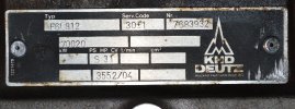
-
Thank you for visiting HeavyEquipmentForums.com! Our objective is to provide industry professionals a place to gather to exchange questions, answers and ideas. We welcome you to register using the "Register" icon at the top of the page. We'd appreciate any help you can offer in spreading the word of our new site. The more members that join, the bigger resource for all to enjoy. Thank you!
You are using an out of date browser. It may not display this or other websites correctly.
You should upgrade or use an alternative browser.
You should upgrade or use an alternative browser.
Deutz 912 injection drip timing degrees
- Thread starter towbar
- Start date
thepumpguysc
Senior Member
- Joined
- Mar 18, 2010
- Messages
- 7,542
- Location
- Sunny South Carolina
- Occupation
- Master Inj.Pump rebuilder
I HATED going out on Deutz calls.!!
The info was always missing..
1st u HAD TO find TDC..
Then make a pointer..
Cuz there’s NEVER a pointer OR numbers..
Then mark the harmonic balancer.. then cut THAT in half, then cut THAT in half..
So your looking at 4 pcs of pie..
THEN cut THAT in half.
Which gives u 45*..
THEN AGAIN IS 22.5*..
So u need to take with you,
An injector puller.
A long rod to put in the removed injector hole to SEE TDC.
A ruler to make straight lines.
A black marker to make those lines..
The phone number of your local Deutz dealer to find the engine degree’s..
& A LOT of patients..
Good luck
I didn't believe it, but 30 is what the manual says. I didn't find the process for finding TDC, the manual starts with that assumed. Basically like TPG says, marking at a precise piston height coming up from both directions, then cut that angle in half.
Ok, the easy way i was taught at Deutz service school is: #1– find true TDC. Find the pointer or make one(sometimes its only a small cast arrow on the timing cover). Remove #1 valve cover(closest to the flywheel), remove starter to access the flywheel ring gear and bar the engine past tdc and insert a 6mm allen key in between the valve stem and the rocker arm on either valve on #1 cyl. Just use the same valve each time. Then bar the engine backwards CAREFULLY until you feel the piston contact the valve. Scratch a mark on the crank pulley aligning with the pointer. Remove the allen key and bar the engine BACKWARD all the way past tdc about 30 or 40 degrees the same amount as before. Repeat the procedure only this time before tdc. With a flexible ruler , halve the distance between the two scratch marks and make a permanent mark. This is TRUE TDC. #2— Measure the outer diameter of the crank pulley (ie. 240mm?) Calculate the circumference—pi x d. Then, the circumference in mm divided by 360 equals the number of mm per degree. This number times the timing degrees(31) beforeTDC will show the mm measurement where you make a mark on the pulley BEFORE TRUE TDC. #3— remove #1 injection line off the pump(Bosch i assume). Remove the side cover off the pump and with the fuel shutoff inoperative, carefully pump up the #1 plunger until the fuel is at the top level of the delivery valve. I used an old injector line bent in a U with an angle-cut end about 4” long and pumped until a drop of fuel was just showing hanging from the end. Then when you bar the engine back toward tdc in the direction of rotation,carefully watch the drop of fuel and the precise moment it starts to grow bigger, is the commencement of injection. Then look at the crank pulley and see how close the 31 degree mark is to the pointer. When they align, the timing is correct. It may take a few tries to get it right. Using the fuel at the top of the delivery valve on the pump may work but it may not be as accurate as with the u-shaped cut-off injector line. Simple, no?
Thanks guys, 56wrench especially, that's a mouthful I'm gonna have to read and re-read. Agree that drip-checking is the only way, it measures the end result and not some contributing technique, there being a huge difference sometimes. I had once made me a real nice degree wheel to stick on the pulley but now I have NO pulley cause I'm gonna 1st-start the engine with the front cover off, probably in April. HOWEVER while twiddling around with the starter I noticed the flywheel teeth and the old lightbulb flashed: "just how many of these are there"? Now I would have supposed that intelligent people would have put 120 teeth which WOULD work remarkably well with 360 degrees but not Deutz, no Sir! 
Initial data is that there are 128 teeth & 129 valleys so after marking compression TDC for Cyl-1 it becomes a matter of turning the crank with a screwdiver exactly to where I want it. This part is what I'm cooking right now, after having just documented a bulletproof TDC method that's easy every time, even in service. My present situatiuon is different from line operation admittedly (flywheel exposed, no front cover).
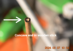
Make the end of a wooden stick concave.
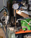
Crank to get valve overlap on cyl-1 (close to compression TDC, piston is near top). Drop the stick in the injector hole and mount gauge on the stick. Note when gauge stops rising turning in normal direction and then when turning in the other direction. Split the beans and mark as compression TDC.

My cam wheel punchmark was already painted white, so I marked its location on the block edge. TYhe flywheel with pass the TDC mark twice in a cycle, this mark says if it's on the compression TDC. Then just for reference I marked with yellow the depression when cyl-6 is at compression TDC. My flywheel is now marked every 10 teeth and I'm next working out the 'Commencement of Delivery' sweet spot now that 31 degrees seems to be the magic number to go for.
Initial data is that there are 128 teeth & 129 valleys so after marking compression TDC for Cyl-1 it becomes a matter of turning the crank with a screwdiver exactly to where I want it. This part is what I'm cooking right now, after having just documented a bulletproof TDC method that's easy every time, even in service. My present situatiuon is different from line operation admittedly (flywheel exposed, no front cover).

Make the end of a wooden stick concave.

Crank to get valve overlap on cyl-1 (close to compression TDC, piston is near top). Drop the stick in the injector hole and mount gauge on the stick. Note when gauge stops rising turning in normal direction and then when turning in the other direction. Split the beans and mark as compression TDC.

My cam wheel punchmark was already painted white, so I marked its location on the block edge. TYhe flywheel with pass the TDC mark twice in a cycle, this mark says if it's on the compression TDC. Then just for reference I marked with yellow the depression when cyl-6 is at compression TDC. My flywheel is now marked every 10 teeth and I'm next working out the 'Commencement of Delivery' sweet spot now that 31 degrees seems to be the magic number to go for.
Ok, the easy way i was taught at Deutz service school is: #1– find true TDC. Find the pointer or make one(sometimes its only a small cast arrow on the timing cover). Remove #1 valve cover(closest to the flywheel), remove starter to access the flywheel ring gear and bar the engine past tdc and insert a 6mm allen key in between the valve stem and the rocker arm on either valve on #1 cyl. Just use the same valve each time. Then bar the engine backwards CAREFULLY until you feel the piston contact the valve. Scratch a mark on the crank pulley aligning with the pointer. Remove the allen key and bar the engine BACKWARD all the way past tdc about 30 or 40 degrees the same amount as before. Repeat the procedure only this time before tdc. With a flexible ruler , halve the distance between the two scratch marks and make a permanent mark. This is TRUE TDC. #2— Measure the outer diameter of the crank pulley (ie. 240mm?) Calculate the circumference—pi x d. Then, the circumference in mm divided by 360 equals the number of mm per degree. This number times the timing degrees(31) beforeTDC will show the mm measurement where you make a mark on the pulley BEFORE TRUE TDC. #3— remove #1 injection line off the pump(Bosch i assume). Remove the side cover off the pump and with the fuel shutoff inoperative, carefully pump up the #1 plunger until the fuel is at the top level of the delivery valve. I used an old injector line bent in a U with an angle-cut end about 4” long and pumped until a drop of fuel was just showing hanging from the end. Then when you bar the engine back toward tdc in the direction of rotation,carefully watch the drop of fuel and the precise moment it starts to grow bigger, is the commencement of injection. Then look at the crank pulley and see how close the 31 degree mark is to the pointer. When they align, the timing is correct. It may take a few tries to get it right. Using the fuel at the top of the delivery valve on the pump may work but it may not be as accurate as with the u-shaped cut-off injector line. Simple, no?
My side cover screws are sealed, I'd rather leave then sealed. My drip tube is already installed, is it necessary to actually see the delivery valve?
I may yet try this too but I didn't want to break the seal on the cover screws, that voids the warranty AND drops the pump value to 'core'. But I did manage a neat FUBAR for my weekend, all the previous markings got done at valve opverlap instead of compression TDC  got work to do tomorrow, it's a good thing we're getting a snowstorm anyway...
That's ok, I'll make you feel better with this. In addition toi first having done it on the wrong TDC, my idea of a wooden stick was a poor one, anyone reading it should discard the whole thing. What happens is that the stick hits the sloping side of the bowl in the top of the piston and if it slips it's unreliable. So then I tried YOUR method but with a 5mm nut instead of a 6mm allen key, put the gauge on the valve rocker and that gave me a very respectable and reliable narrow splay around the rise.
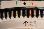
The refrence tooth is green, the first gauge move on the way up in the normal CCW direction is red, the sec ond one in reverse CW direction is green. Compression-TDC is thus at the black arrow with a VERY high degree of precision.
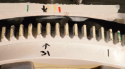
Then I marked off the end of the 10th valley (tooth) to the left and the 1/3 after the next 7th for 31 degrees (17-1/3 valleys). THAT is the drip target.
But I'm not doing the drip yet. I don't have a manual pressure pump, what kind of PSI am I looking for? I do have an injector tester I could use. If I read all the guidance correctly I should
- start at about 90 degrees before Compression-TDC
- maintain the required pressure while cranking toward it
- see a first drop forming at 31 degrees.
What am I to see after 31 degrees, a flow?

The refrence tooth is green, the first gauge move on the way up in the normal CCW direction is red, the sec ond one in reverse CW direction is green. Compression-TDC is thus at the black arrow with a VERY high degree of precision.

Then I marked off the end of the 10th valley (tooth) to the left and the 1/3 after the next 7th for 31 degrees (17-1/3 valleys). THAT is the drip target.
But I'm not doing the drip yet. I don't have a manual pressure pump, what kind of PSI am I looking for? I do have an injector tester I could use. If I read all the guidance correctly I should
- start at about 90 degrees before Compression-TDC
- maintain the required pressure while cranking toward it
- see a first drop forming at 31 degrees.
What am I to see after 31 degrees, a flow?
thepumpguysc
Senior Member
- Joined
- Mar 18, 2010
- Messages
- 7,542
- Location
- Sunny South Carolina
- Occupation
- Master Inj.Pump rebuilder
After 31* it’ll shut off completely.. then restart the flow again..
This pump has no viewport to eyeball any timing-mark that I can find, no timing-pin either on the pump or on the block like on a Cummins. Unless I find a way to micrometer a rising plunger or something of that nature I have no alternative but to drip-time it. For that I need some drill like:
1 - Set compression-TDC on cyl-1
2 - connect handpump output to injection-pump inlet port
& plug relief-valve port
3 - install drip-tube in lieu of #1 injection line on injection-pump
4 - back the crank (CW from rear) to about 90 degrees before CTDC
5 - apply XYZ psi of fuel pressue to injection-pump inlet port
6 - observe flow (or is it no-flow?)
7 - slowly bar the crank toward CTDC (CCW from rear) & watch
drip-tube outlet
8 - approaching 31 degrees before CTDC expect to see
a first (or is it last?) drop forming, MARK pulley or flywheel
THIS is "Commencemnet of Delivery"
9 - if you overshoot the CoD expect to see flow (or is it no-flow?)
resume as you bar the crank further & start over at #1
I've been googling for an hour, I cannot fathom how a major manufacturer like Deutz could leave such a vacuum of coherent guidance uncorrected!
thepumpguysc
Senior Member
- Joined
- Mar 18, 2010
- Messages
- 7,542
- Location
- Sunny South Carolina
- Occupation
- Master Inj.Pump rebuilder
It should go from a stream to a drip every few seconds..= port closure..
It’ll go from a stream, to a fast drip, to a slow drip, to pc, to stop.
U HAVE TO remove the side cover (2-4mm Allan Screws) inorder to put the pump on the correct cylinder..
Get it on the bottom of its stroke, coming up..
It’ll go from a stream, to a fast drip, to a slow drip, to pc, to stop.
U HAVE TO remove the side cover (2-4mm Allan Screws) inorder to put the pump on the correct cylinder..
Get it on the bottom of its stroke, coming up..
We're not talking about the same procedure but I'll get on it tomorrow AND git'er done!
I've uploaded to imgur the significant steps7-11 of the drill that "I" have, there ARE differences. For example the manual procedure says to connect the hand-pump to the injection-pump inlet and not to any cylinder. I'll open the cover and see what there is inside, how to connect some pump to cylinder-1 and I'll be back.
step-7 step-8 step-9 step-10 step-11 https://imgur.com/EsYw2Ft.png
I hope I didn't screw up these links, I can put up the other 18 of 23 but these are the key ones. Later.
Changed my mind, I'm not going to to open the seals on my freshly rebuilt pump ($3000) or start removing parts that I risk putting back together wrong just to time the injection. The procedure in the manual exists and must be good or it wouldn't be there so I'm back where I was:
- find out the pressure in the hand-pump
- buy a proper hand pump for the job (asked around, nobody has one)
- have a clear understanding of exactly what to expect and what to do throughout the entire procedure.
This is likely to take time but is free of potentiallly expensive FUBARS of which I've had my share in the past. I'll put up the rest of the images on imgur and then continue googling.
Since this morning I've found out that the pressure is a nominal 30 bar i.e. 430 psi. so your idea might just be ok. I'm waiting for more links, MAYBE someone does sell just the right article without charging an arm and a leg.

