• Thank you for visiting HeavyEquipmentForums.com! Our objective is to provide industry professionals a place to gather to exchange questions, answers and ideas. We welcome you to register using the "Register" icon at the top of the page. We'd appreciate any help you can offer in spreading the word of our new site. The more members that join, the bigger resource for all to enjoy. Thank you!

Cribbing:

1693TA

Senior Member
Joined
Feb 27, 2010
Messages
2,687
Location
Farmington IL
Occupation
FAA Radar Engineer, (Retired)
Running with the trench, or grease pit idea sounds interesting to me. Say a 30" wide finished trench/pit width with concrete block sidewalls atop a poured floor enclosed by a space frame clear shell. I'm thinking the tops of the sidewall(s) transition from vertical to the horizontal plane be topped with 5X5X3/4" angle steel around it's perimeter to permit two sliding, or rolling jacking beams to be utilized if needed which would be easily removable. Steps at either one, or both ends to facilitate entry/exit to the trench. This jacking beam idea comes straight from my automotive frame rack and they were used a lot lifting, twisting, and pushing things back into shape.

Around here they don't tax yard storage sheds, nor the same with a concrete floor. They do tax buildings so would need to make this appear to be a shed if elected to enclose. I don't know at this point but it would be fairly easy to fabricate an enclosure which could be easily taken down. If clear fiberglass panels such as these shown in the link were utilized with treated lumber for the space frame, the cost wouldn't be that great. A roll up door would most likely be utilized for this affair.

https://www.menards.com/main/buildi...roof-panel/1592834/p-1444424087688-c-5819.htm

I'll have to speak with the zoning board before going any further but I'm sure an open concrete pad and trench would have no effect. Don't know about laws/rules pertaining to an open trench, or even a chain guarded trench if outdoors. Enclosed would be no problem.

Little thing yet to figure out but I'm kind of favoring this approach. I have the ground needed available so may run with it.
 

Willie B

Senior Member
Joined
Jan 2, 2016
Messages
4,063
Location
Mount Tabor VT
Occupation
Electrician
Mine is inside the garage. I used 8" thick poured concrete walls. The floor is on top of well prepared compacted gravel. At the pit area the floor is 8" thick. Inner form walls were left in place & 3 x 3" strips were fastened to the forms. When first built, I covered with 3" thick oak planks sawed with a chainsaw & Alaskan sawmill. They were heavy & didn't always get put back covering. I later got aluminum diamond plate decking with 3 2 x 4 aluminum channel joists in each. Each of four covers weighs about 50 LBS.
 

1693TA

Senior Member
Joined
Feb 27, 2010
Messages
2,687
Location
Farmington IL
Occupation
FAA Radar Engineer, (Retired)
I have a good friend in CT that has a pit in his garage and rebuilds antique trucks. He finds it very useful also. His is set up like they used to do alignment pits with the front being very expanded and open for working under front ends. No way to jack anything other than a tire clear of the floor for changing.

Floor in my shop is 9" thick on top of well compacted fill sand over virgin ground. Did this myself but there are heating coils in the floor so really limited to what I can do inside the main shop area. Just to the south of my outside wash bay is the pump house for my water supply. About 20 feet IIRC. This is a good well but is not being utilized, but both water, and electrical piping are lain under the slab that is the outside wash bay. This new concrete pad would go over those pipes but they could easily be tapped for supplies.

I like the aluminum trench covers. That would be light enough to handle by oneself so it didn't stay open. If enclosed really no issue. You have any problems with ground water penetration? I installed a well and sump pump in my downdraft air trench but it's never been wet, nor had any water in it. I think I'm just above the water table as the inside wash bay just on the other side of the wall always has water, but the level is below the air trench floor. I've not washed a car back there in many years.
 

Welder Dave

Senior Member
Joined
Oct 11, 2014
Messages
12,611
Location
Canada
I thought I read several years ago that pits in garages weren't allowed anymore due to the possibilty of someone falling into it. Maybe if it had a suitable cover when not being used is acceptable? Would want to look into it for sure. I seem to recall someone wanted to put one in his shop on a farm.
 

1693TA

Senior Member
Joined
Feb 27, 2010
Messages
2,687
Location
Farmington IL
Occupation
FAA Radar Engineer, (Retired)
I think you may be correct. However there are still several in use but now if not in use they are either covered, or a chain barrier is erected if left open. I still see several in use predominantly at the quick lube establishments. They are always open but really not a public space. The entrance, and exit are both cordoned off to unrestricted access.
 

Welder Dave

Senior Member
Joined
Oct 11, 2014
Messages
12,611
Location
Canada
I think quick lube and mechanics shops can still use them but customers aren't allowed in the shop or have to stay in their vehicles. Quite a few years ago I dug an alignment pit at a Goodyear commercial truck center. It was pretty much 5' wide, the width of my bucket, before being cemented in so probably about 4' wide or a little better when finished. Some pits have a pipe rail about 6" high along the sides on top just so a vehicle can't accidentily drop a wheel in.
 

OzDozer

Senior Member
Joined
Jan 18, 2007
Messages
2,207
Location
Perth, Western Australia.
Occupation
Semi-Retired ..
1693TA - Getting back to your cribbing and tractor lifting questions and ideas - this brought back the memory of a Cat tractor lift tool puzzle that I picked up some years ago.

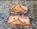
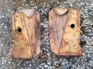
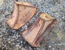
I bought some items at auction and amongst them was these 4 weird-shaped, fabricated, multiple curved steel blocks.

There was no indication from anyone or anything that came with the sale as to what they were.
After some searching, I found a Cat part number stamped into one of the blocks. The number is 9S27.

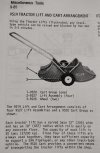
Going to my older Cat tool guide, I found this tool listing of a 9S19 "Tractor lift arrangement" - which comprises these 4 steel blocks, plus a wheeled cart to move them around (there was no sign of the cart in the auction items).

However, despite a short description in the Tool guide, I have never been able to figure out how this setup was supposed to operate - as the description is quite cryptic, and there are no photos anywhere of the tractor lift arrangement in use.

Do you or any other HEF members know anything of this setup and how it actually operates?

It might as well be a Chinese puzzle to me, because despite looking at and studying the blocks for some time, I still can't figure out how they were designed to be used?
 

Attachments

  • 9S0027-4.jpg
    9S0027-4.jpg
    319.5 KB · Views: 18
  • 9S0027-3.jpg
    9S0027-3.jpg
    300.6 KB · Views: 18
  • 9S0027-2.jpg
    9S0027-2.jpg
    325.4 KB · Views: 16
  • 9S0027-1.jpg
    9S0027-1.jpg
    167.9 KB · Views: 18

OzDozer

Senior Member
Joined
Jan 18, 2007
Messages
2,207
Location
Perth, Western Australia.
Occupation
Semi-Retired ..
Here is the Tool guide photo and description of the 9S19 Tractor lift arrangement.
 

Attachments

  • 9S0027-5.jpg
    9S0027-5.jpg
    123.6 KB · Views: 21

1693TA

Senior Member
Joined
Feb 27, 2010
Messages
2,687
Location
Farmington IL
Occupation
FAA Radar Engineer, (Retired)
1693TA - Getting back to your cribbing and tractor lifting questions and ideas - this brought back the memory of a Cat tractor lift tool puzzle that I picked up some years ago.

I bought some items at auction and amongst them was these 4 weird-shaped, fabricated, multiple curved steel blocks.

There was no indication from anyone or anything that came with the sale as to what they were.
After some searching, I found a Cat part number stamped into one of the blocks. The number is 9S27.

Going to my older Cat tool guide, I found this tool listing of a 9S19 "Tractor lift arrangement" - which comprises these 4 steel blocks, plus a wheeled cart to move them around (there was no sign of the cart in the auction items).

However, despite a short description in the Tool guide, I have never been able to figure out how this setup was supposed to operate - as the description is quite cryptic, and there are no photos anywhere of the tractor lift arrangement in use.

Do you or any other HEF members know anything of this setup and how it actually operates?

It might as well be a Chinese puzzle to me, because despite looking at and studying the blocks for some time, I still can't figure out how they were designed to be used?
I have never seen anything like them myself but I will be over to Altorfer, (Cat dealer) and show these photos to a guy that's been there eons to glean anything for you.

He's another I really enjoy yakking with over older equipment. Kind of a personal tie there too as he's the guy that put the u/c under my Allis when the original owner traded it in on a new Cat back in 1995. This was just before the guy I purchased it from bought it from them.
 

Willie B

Senior Member
Joined
Jan 2, 2016
Messages
4,063
Location
Mount Tabor VT
Occupation
Electrician
Ford (in the 9N era) sold devices cradled the axle & you chained them to the wheel. There was a link front to rear as front had no power. Rig them & you lifted the tractor wheels off the ground.
 

Willie B

Senior Member
Joined
Jan 2, 2016
Messages
4,063
Location
Mount Tabor VT
Occupation
Electrician
I think quick lube and mechanics shops can still use them but customers aren't allowed in the shop or have to stay in their vehicles. Quite a few years ago I dug an alignment pit at a Goodyear commercial truck center. It was pretty much 5' wide, the width of my bucket, before being cemented in so probably about 4' wide or a little better when finished. Some pits have a pipe rail about 6" high along the sides on top just so a vehicle can't accidentily drop a wheel in.
My first pit was correct width for a CJ2A Jeep with 6.00-16 tires. Newer Jeeps had wider tires & did not fit as flawlessly. I painted a stripe along the sides to lean out & see where the tires needed to go.

Dad was putting "the white Jeep" in the garage once in a hurry & dropped one front wheel in. Surprisingly little damage!
 

Welder Dave

Senior Member
Joined
Oct 11, 2014
Messages
12,611
Location
Canada
I think the hole in them is a clue. Maybe you pull a few track bolts or a pad and use studs that fit the holes to mount them and driving the machine, it rolls up on the curve of the blocks? It looks like when the flat part with the hole is horizontal there is a short section opposite that is parallel that they sit on when in use. They kind of pop into to place. It could also explain why they aren't real common. Not a very big surface area to be sitting on. You'd need a really strong floor so you wouldn't punch holes in it.
 
Last edited:

OzDozer

Senior Member
Joined
Jan 18, 2007
Messages
2,207
Location
Perth, Western Australia.
Occupation
Semi-Retired ..
The tool description says the blocks have a curved base 12" wide with an 18" radius, which "rolls easily on any concrete floor".

So, based on that description, they're designed to roll on their wide curved bottoms - I just can't picture how that would operate.

I'm thinking the concave section matches the curve of the track at a front idler or sprocket, and you drive the tractor up onto two blocks, until it's sitting fully on the more pointed top of the blocks.
But I can't figure how the tractor would climb onto the second pair of blocks.

Do you back up onto the second pair of blocks? - or keep driving forward onto the other pair? And where does the "rolls easily on any concrete floor" come in? That indicates a rolling motion is required to assist in the lifting.

The curved bottoms remind me of the local stock crate or grain bin lifting/removal device, that is a local design. It's called a Hobbs Hoist, after the inventor.

This device uses a set of varying-radius supports at the four corners of the crate or bin, which are pinned at their tops by sliding two pieces of 75mm (3") pipe through them, and through four larger diameter pipe sections on the crate or bin.

Once the four supports are pinned in place, you back up, using the truck headboard as the "push blade", and the varying radius of the supports lifts the crate or bin around 75-150mm (3"-6") - whereby you lock the supports with two rods and chains that tie the tops of the front supports to the bottoms of the rear supports.
You're then free to drive off, leaving the crate or bin suspended on the supports.
Loading the crate or bin back on simply involves reversing the unloading process.

With the Cat 9S19 lifting devices, I found a Cat "lifting/blocking/clamping" publication, which states that the Cat tripod base, tube-style tractor stands, can be used to support a tractor after its been raised by the 9S19 lifting devices - which seems to indicate the tractor can be rolled back and forth on the 9S19 lifting devices, which must have to happen, to allow the tractor to be lowered onto the tube-style stands.

I'm thinking the holes in the devices are simply there for the cart to attach to the devices. Possibly projecting pins on the cart, and the blocks are simply lifted onto the pins, to clear the floor?


1693TA

Senior Member
Joined
Feb 27, 2010
Messages
2,687
Location
Farmington IL
Occupation
FAA Radar Engineer, (Retired)
I posted this earlier today in the wrong thread. Here it is corrected:

I'd meant to update this but have quite a bit moving along with the new year coming and forgot. Fingers are still in a lot of pies but starting to rescind.

The pit idea is moving forward. I could do this myself but going to hire a couple of young bucks to do this work. Talked to the taxing body about it and if I don't install a concrete floor, or plumbing and water in the interior of a steel, or wood space frame shell utility shed/building such as I'm wanting, there will be nothing additional for them to tax as considered "non permanent". Basically another "yard barn" as called around here. Posts such as a pole barn uses are still considered "non permanent" but rather "anchors" to keep the structure from blowing away.

Thinking I'll build a rectangular box in the ground, (pit) of concrete, then compact and gravel much the same as you would a roadbed around the pit keeping elevation low enough to overlay the gravel with planking. This is just an idea. I would most likely incorporate a rolling "jacking beam" into the design of the pit perimeter. If doing this, the complete interior except the pit floor and walls would fit their vision of a non permanent structure. The pit would be masonry with a steel upper support perimeter for the beam to roll upon. I think the structure about 16' in width, 28' in length with 12' sidewalls, and having a 2/12 pitch roof would be about perfect for fitting my dozer or a semi tractor in for servicing. A personnel walkdoor in a sidewall, and 12' wide coil up door in the endwall with a power operator would be good. No need for a drive through setup with this shed idea. Just pull straight in, back out.

I'd insulate the roof to keep the condensation at bay but have to see how much use would be actual before doing anything with the side, and end walls concerning insulation.
 

Welder Dave

Senior Member
Joined
Oct 11, 2014
Messages
12,611
Location
Canada
It appears the blocks will work with all sizes of machines so the radius won't match every sprocket or idler. I can't see them gripping on a concrete floor by themselves. I can't see how they could be set up to lift a machine in 1 shot. Lifting 1 end up and then reversing direction for the other end makes the most sense unless you lift the front of a machine with the blade and then put the blocks under. Maybe Tctractor knows how they work? They can't have been common.
 

John Shipp

Senior Member
Joined
Mar 5, 2015
Messages
643
Location
England
Occupation
forestry contracting
You don't think those lifting things simply get wedged as a pair each side at the rear, and then the grouser lifts tractor up going in reverse? Then push blade down to lift front?

Weird looking things though.
 
Top