• Thank you for visiting HeavyEquipmentForums.com! Our objective is to provide industry professionals a place to gather to exchange questions, answers and ideas. We welcome you to register using the "Register" icon at the top of the page. We'd appreciate any help you can offer in spreading the word of our new site. The more members that join, the bigger resource for all to enjoy. Thank you!

CAT 416c tach & hour meter

backspacer

Member
Hey, my tach and hour meter stopped working suddenly. I checked continuity from tach and hour meter to alternator and its good. Power and ground is good. Serial # 4ZN02115. What am I missing? Also, what year is this 416c? Thanks in advance
 

Nige

Senior Member
Do you have an electrical schematic.? If not, do you want one.?

Your machine was built April 1997.
 

backspacer

Member
I have the parts manual but not any schematics, so yes I would love one. Any advice on where to start since the simple check of continuity checks out?
 

Nige

Senior Member
I'll send you the electrical schematic. Keep an eye on your messages.
I have the parts manual but not any schematics, so yes I would love one. Any advice on where to start since the simple check of continuity checks out?
Not really. But if you locate the tachometer & hourmeter on the schematic and start working back towards wherever the power/signal comes from you should find something common.
 

backspacer

Member
I do not have a schematic in front of me but you could check the Tach output on the alternator.
I have checked continuity to tach from alt and its good. If there is supposed to be some other type of signal, let me know how to check it please.
 

backspacer

Member
I'll send you the electrical schematic. Keep an eye on your messages.

Not really. But if you locate the tachometer & hourmeter on the schematic and start working back towards wherever the power/signal comes from you should find something common.
Thanks for the schematic. After a simple trace, the single wire has good continuity to both the tach and hour meter. It's one wire from the alternator that splits into a Y under instrument panel that then goes to tach and hour meter. What type of signal is coming from the alt? Is there some other way I should check instead of just continuity?
 

Nige

Senior Member
I have checked continuity to tach from alt and its good.
Have you checked the wire under load using a test light connected to/from batt+ & ground.?

You will need to disconnect wire 450 Yellow at both the alternator end and the service meter/tacho end.
It's not unknown for a wire to show continuity on a multimeter because it literally only needs one strand to do that, but put a load on it and it breaks down.
 
  • Like
Reactions: mks

Coaldust

Senior Member
OP,
What kind of signal, you ask?

You will be looking for an A/C signal in the 0-30volt spectrum that changes with engine rpm.

Don’t get wrapped around the axle on actual voltage. You either have a fluctuating signal, or you don’t. If you don’t have a signal at the Alternator tachometer terminal, most common is a bad diode trio. Because that’s how the stator tap gets to the tach terminal.
 

backspacer

Member
OP,
What kind of signal, you ask?

You will be looking for an A/C signal in the 0-30volt spectrum that changes with engine rpm.

Don’t get wrapped around the axle on actual voltage. You either have a fluctuating signal, or you don’t. If you don’t have a signal at the Alternator tachometer terminal, most common is a bad diode trio. Because that’s how the stator tap gets to the tach terminal.
The yellow wire that runs straight to the hour meter and tach has nothing on it. I checked right at the connector on the alternator and nothing, even when reving up the engine. You say a bad diode trio? Where is that and is it replaceable or do I need a new alternator? Thanks
 

Nige

Senior Member
You say a bad diode trio? Where is that and is it replaceable or do I need a new alternator?
I would say #6 on the attachment but the electrical experts should confirm that.
This is providing your alternator is OEM and has not been replaced with a "will fit" at some point during the life of the machine.
 

Attachments

  • 105-2813 Alternator Gp.pdf
    183.4 KB · Views: 3

Coaldust

Senior Member
You have a few ootions. You could take the alternator apart, replace the diode trio and install new brushes while you are in there. You could purchase a replacement or have your favorite electrical shop rebuild it.
 

backspacer

Member
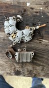
so I got the rectifier (top part in pic) and regulator off (bottom part in pic). Is there a way to check to see which one is bad? The connector that goes to the tach and hour meter plugs into the regulator. I can't find the rectifier anywhere online except for CAT, about $120. Haven't searched for the regulator. Best guess as to which is bad?
IMG_8057.jpeg
 

Coaldust

Senior Member
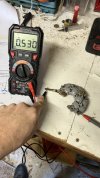
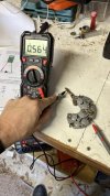
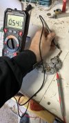
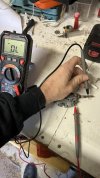
You can check the diodes in the rectifier bridge individually with an DVOM w/diode test feature. They should have about .5v of voltage drop.

You can even check the VR by using a 12 volt car battery, DVOM,some jumper wires and a battery charger.

It’s too much for me to peck out with my smart phone. There is a ton of YouTube videos that demonstrate it.
 

backspacer

Member
Looks like one of the diodes is bad. All were in the .5 range except one. Anybody know where to get this part other than CAT? Yes, I have searched the web with the part number ;)

IMG_8059 (Small).jpgIMG_8060 (Small).jpgIMG_8061 (Small).jpgIMG_8062 (Small).jpg
 

Coaldust

Senior Member
Easiest way would be to convert the Cat number to an Asin number, then go to EBay.

It’s probably a 204502447515 diode assembly. But, I would verify that. It may have a number on it.
 
Top