masterwelder
Well-Known Member
2007 CJC05477
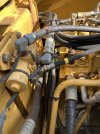
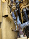
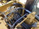
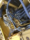
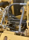
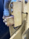
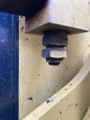
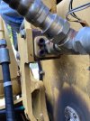
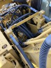
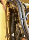
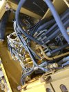
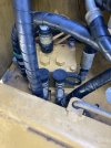
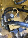
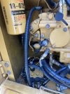
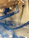
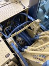
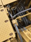
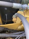
Pretty certain my excavator is set up for hammer plumbing only with one way flow. Right now I have two feed lines (pressure) coming from the main valve block, one from each, near outer-side, banks of the main valve block coming together at a tee then into a machined steel coupling (for lack of a better description) out of coupling out to stick.
The return comes into its own machined coupling then to a tee where one hose goes across by the pressure machined block and terminates. The other hose continues behind the valve bank and connects to what I would describe as a main connection block that goes to the tank.
My description is no doubt leaving out and or improperly describing some parts but I’m trying to see if it rings a bell with anyone. I would like to add a thumb and tilt grading bucket to this machine.
For aux hydraulic cab controls I only have what looks like a on/off foot dead man switch. I want a thumb control on the joystick if possible.
Anyone familiar with the plumbing I have and/or what I want?
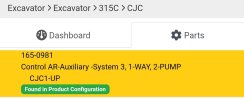
This looks like a factory setup to me. I haven’t had a chance to look in SIS yet.


