Alright guys here's the story. A friend of mine asked me to work on his bulldozer and I agreed. I am a tractor mechanic and have never work on a bulldozer before. So we bought the service manual and the operation and test manual. He felt a pretty bad vibration and heard a loud pop. He knows when things are not right. We check the filters and they were full of brass so we pulled the pumps and wheel Motors and had them rebuilt. They found in the wheel motor the main shaft had fractured and the pumps had ingested metal which caused the fresh brass shavings. We got them back and installed them and the calibration was failing. We talked to the guy about the pumps and he told us about the electronic valves. He had a friend that only does electronic valves for hydrostatic pumps we talked to him and found out he does John Deere's remanufacturing of their OEM valves for the reman pumps. So we sent the valves off and had them gone through. He found the valves where worn beyond repair. He mailed us back one brand new valve and one with the guts replaced. We have put everything back in and tried to recalibrate. Now it goes all the way to the last step and throws a code of F3C8. Which to my understanding is the right track electronic valve issue during calibration. Both tracks run in sync as far as I can tell. Another issue I'm concerned about is the trans pressure Guage Falls slightly when you go to move the tracks. What can I look for to help correct this problem and have the machine calibrate properly?

-
Thank you for visiting HeavyEquipmentForums.com! Our objective is to provide industry professionals a place to gather to exchange questions, answers and ideas. We welcome you to register using the "Register" icon at the top of the page. We'd appreciate any help you can offer in spreading the word of our new site. The more members that join, the bigger resource for all to enjoy. Thank you!
You are using an out of date browser. It may not display this or other websites correctly.
You should upgrade or use an alternative browser.
You should upgrade or use an alternative browser.
2000 650h lgp
- Thread starter krauseb
- Start date
Alright guys here's the story. A friend of mine asked me to work on his bulldozer and I agreed. I am a tractor mechanic and have never work on a bulldozer before. So we bought the service manual and the operation and test manual. He felt a pretty bad vibration and heard a loud pop. He knows when things are not right. We check the filters and they were full of brass so we pulled the pumps and wheel Motors and had them rebuilt. They found in the wheel motor the main shaft had fractured and the pumps had ingested metal which caused the fresh brass shavings. We got them back and installed them and the calibration was failing. We talked to the guy about the pumps and he told us about the electronic valves. He had a friend that only does electronic valves for hydrostatic pumps we talked to him and found out he does John Deere's remanufacturing of their OEM valves for the reman pumps. So we sent the valves off and had them gone through. He found the valves where worn beyond repair. He mailed us back one brand new valve and one with the guts replaced. We have put everything back in and tried to recalibrate. Now it goes all the way to the last step and throws a code of F3C8. Which to my understanding is the right track electronic valve issue during calibration. Both tracks run in sync as far as I can tell. Another issue I'm concerned about is the trans pressure Guage Falls slightly when you go to move the tracks. What can I look for to help correct this problem and have the machine calibrate properly?
The only thing I can speak to is the last item, any hydrostat system will show a slight drop in charge pressure when beginning to move, this is the hot oil shuttles in the motors opening to flush hot oil out of the loop through the motor case to the cooler. Normally see 20-30psi drop but this can vary a lot, just a general rule.
Does the machine track straight at low and high speeds (above and below 2.0)? Hows about if you unplug one of the speed sensors on the hydraulic motors?
If you have the service manuals, I'd do a PCP test to make sure the pump controllers are nulled correctly, especially if they were rebuilt. Check the PCP null FIRST, then then try a PDCV test to neutral out the pump controls.
F3C8 is right track forward calibration too low. You're calibrating the mA to the pump in low and high speed. If you're failing at the last part which is high speed, the minimum displacement screw on your motors might be set wrong. Since the 650H has 2 position motors, if its shifting to too low a displacement in high speed, it'll take less mA from the pump for calibration causing it to fail.
Theres a procedure in the service manual to adjust the min angle position in the motors and you'll be able to see the speed readout on the TCU controller screen. I'd check that your motor displacement stops are set right and your speeds are in range.
Agree with the other poster above, the charge pressure will drop ~30psi when shifting into gear from neutral because oils is being routed into the flushing circuit to cool the motor cases.
Okay got back to the Dozer. Check the PCP and they were all in spec. Now during the motor adjustment the manual gives 2 specs. Both say to use a test harness that will supply 5 volts to the PCP. My question is do I ignore the lower-spec and go with the Higher One with Speed 3 and wide open throttle as that should Supply 5 volts to the PCP? Also the operation test manual says there is a list of codes within it. I believe in my manual these codes are non-existent as I have looked and cannot find them. Is there a specific page they are located?
Use the lower spec for 5mph (3230-3680rpm). That was the default setting from the factory. Do you know the machine SN?
Your manual might not have the list of codes. Sometimes if you don't successfully complete a TCU calibration, the controller will set some codes that get wiped out the next time you start a calibration. These are just alerting that a previous calibration did not successfully finish.
Before you adjust your min angle stops, can you check what motor speeds you're getting on the controller screen when you fully stroke the PCP's?
Both my motor speeds we're about 1800 RPM with the pump fully stroked and in Speed 3 the codes I got the first 3 attempts at a calibration are F3D7, F3E7, F3N1, F3M1. I got these before I got to the track speed part. The last part I got F3C8 and F3D8. I increased motor speeds to 2300 RPM. Tomorrow I will increase motor speeds to about 3400 RPM and try calibration again.
F3D7 is right pump calibration failed
F3E7 is left pump calibration failed
F3M1 and F3N1 are for left and right speed sensor voltage out of range, possible mistrack
F3C8 and F3D8 are the front and rear pump failed low speed calibration. I'd expect to see these codes if the min displacement isn't adjusted correctly.
When you're adjusting your speeds, you should see 2165-2385rpm when the motors are not shifted (speed at 2.0) and about 3230-3680rpm when the motors are shifted (speed at 3.0). If you have help, there is a small lever on the pump PCP control that you can move to manually drive the pumps to max flow and have someone watch the speeds on the TCU screen.
Last edited:
Checked fspd and rspd and set them to med. I adjusted the motors to 3400 rpm. I tryed calibration and it failed with a f3a7. I tryed it again and it went through the low track spd part and the tcu said save and froze. I pushed and held all the buttons but nothing changed. I cut the key and restarted to find f3e8 f3c8 f3d8 f3a8. I manually stroked the pumps and watched the rpm. The left track ran the same rpm in both f and r. The right track r was several hundered rpm faster than f. My thinking is that i have the null or the pcp misadjusted. Is this a safe assumption? Also is there anywhere i can find a list of service codes and explanations?
You can double check the null again, but if you're manually stroking the pumps they should go to max flow even if the null is off.
Are you able to see the calibrated pump PCP mA under DIAG in the TCU screen? If I knew what numbers the achine was calibrating at it might help narrow down the issue.
What type of motor speeds were you seeing when you manually stroked the pumps in Fwd and Rvs for both sides?
I'll get you a list of codes next time I'm at my work computer
Here is the flowchart for calibration failures and general DTC codes. I can send you a PDF of all the 650H DTC's and recommended troubleshooting steps if you send me your email address - its about 200 pages.
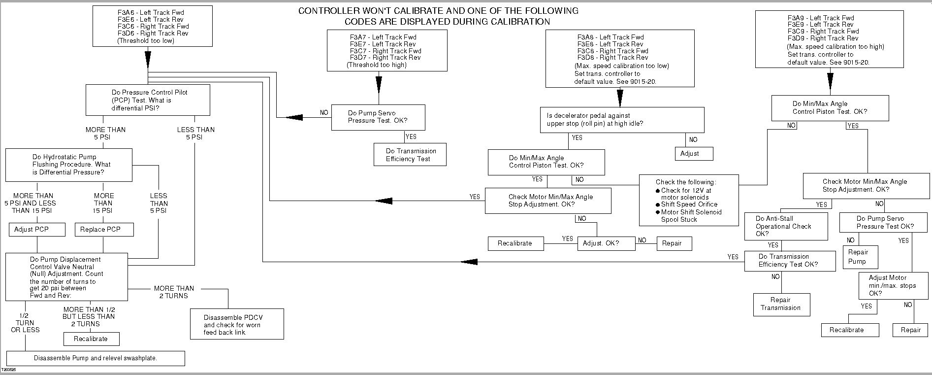
Transmission Controller Diagnostic Trouble Codes And Calibration Codes
NOTE:
Transmission controller diagnostic trouble codes will display when malfunction occurs.
NOTE:
When diagnostic trouble code appears, shut engine off and restart engine to check if diagnostic trouble code is an intermittent problem. Investigate circuit failure identified by diagnostic trouble code.
The diagnostic trouble code number is indicated by an F3 plus two other digits.
The letter F means that a fault has occurred. The number 3 means the transmission controller has diagnosed a problem in the transmission area and has sent a diagnostic trouble code to the controller window to be displayed.
The last two digits of diagnostic trouble code number indicate specific failures.
If the third digit of the diagnostic trouble code number is (1), it indicates that at least one of the sensor voltage wires is less than 4.75 volts or more than 5.25 volts.
If the third digit of the diagnostic trouble code number is (2), it indicates that battery voltage is less than 9 volts or more than 16.5 volts.
If the third digit of the diagnostic trouble code number is (3), it indicates a problem with B2 FNR Sensor.
If the third digit of the diagnostic trouble code number is (4), it indicates a problem with B5 Left and Right Steer Sensor.
If the third digit of the diagnostic trouble code number is (5), it indicates a problem with B1 Decelerator Sensor.
If the third digit of the diagnostic trouble code number is (6), it indicates a problem with B4 Transmission Speed Control Sensor.
If the third digit of the diagnostic trouble code number is (7 or M), it indicates a problem with B7 Left Track Motor Speed Sensor.
If the third digit of the diagnostic trouble code number is (8 or N), it indicates a problem with B3 Right Track Motor Speed Sensor.
If the third digit of the diagnostic trouble code number is (9), it indicates a problem with B6 Hydrostatic Pump Speed Sensor.
If the third digit of the diagnostic trouble code number is (A or E), it indicates a problem with B8 Rear (LH) Pump Pressure Control Pilot (PCP).
If the third digit of the diagnostic trouble code number is (C or D), it indicates a problem with B9 Front (RH) Pump Pressure Control Pilot (PCP).
If the third digit of the diagnostic trouble code number is (P), it indicates a problem with S20 Park Lock Lever Switch and/or S4 Brake Pedal Switch.
If the third digit of the diagnostic trouble code number is (H), it indicates a problem with S3 Neutral Start Switch.
If the third digit of the diagnostic trouble code number is (J), it indicates the F3J4 diagnostic trouble code was displayed when exiting calibration with out completion. Wrong harness. Wrong transmission controller, or when a new transmission controller has been installed and not calibrated.
If the third digit of the diagnostic trouble code number is (K), it indicates a problem with Y3 (RH) Motor Shift Solenoid.
If the third digit of the diagnostic trouble code number is (L), it indicates a problem with Y4 (LH) Motor Shift Solenoid.
If the third digit of the diagnostic trouble code number is (R), it indicates a problem with B27 Reverse Speed Ratio switch.
If the third digit of the diagnostic trouble code number is (T), it indicates a problem with B4 Transmission Speed In Grip (SIG).
If the fourth digit of the diagnostic trouble code number is (0, 2, 3, or 5), a open circuit, shorted circuit, or no feed back is indicated. Do not attempt calibration. See diagnostic trouble codes.
If the fourth digit of the diagnostic trouble code number is (1 or 4), a calibration error or circuit failure is indicated. Access main menu and select DIAG in transmission controller. Compare calibrated values to real time values! If values don't match RECALIBRATE.
NOTE:
If diagnostic trouble code (311, 314, 321, or 324) is displayed DO NOT CALIBRATE, see diagnostic trouble codes.
If the fourth digit of the diagnostic trouble code number is (6, 7, 8, or 9), it is the result of calibrating indicating there is a failure. The failure must be fixed before calibrating again. See diagnostic trouble codes.
There are sixty two “62” Diagnostic Trouble Codes.
The following twenty two “22” Diagnostic Trouble Codes will display in transmission controller window, will be stored in memory and the “Check Diagnostic Trouble Code” light on the display monitor will be ON: F311, F314, F321, F324, F330, F331, F334, F335, F340, F341, F344, F345, F3A0, F3A5, F3C0, F3C5, F3D0, F3D5, F3E0, F3E5, F3H1, F3H4.
The following forty “40” Diagnostic Trouble Codes will display in transmission controller window and will be stored in memory: F350, F351, F354, F355, F360, F361, F364, F365, F370, F372, F373, F375, F380, F382, F383, F385, F390, F392, F393, F395, F3P0, F3P5, F3M1, F3M4, F3N1, F3N4, F3J0, F3J1, F3J4, F3J5, F3K3, F3L3, F3R0, F3R1, F3R4, F3R5, F3T0, F3T1, F3T4, F3T5
There are forty four “44” Calibration Codes.
The following forty four “44” Calibration Codes will display during calibration: F336, F337, F338, F339, F346, F347, F348, F348, F356, F357, F358, F359, F366, F367, F368, F369, F396, F397, F398, F399, F3A6, F3A7, F3A8, F3A9, F3E6, F3E7, F3E8, F3E9, F3C6, F3C7, F3C8, F3C9, F3D6, F3D7, F3D8, F3D9, F3H6, F3H7, F3H8, F3H9, F3T6, F3T7, F3T8, F3T9.
!CAL Displayed On Controller and Check Diagnostic Trouble Code Light Flashing
This displayed on the controller indicates that calibration was not completed.
Last edited:
My email is krauseb24@gmail.com. I double checked and null and pcp adjustment. Everything seemed right. In the DIAG screen both the pumps show 0 millivolts all other functions show values. These were measurments taken at wide open throttle. On the left pump millivolts Speed 2 and forward was 600 and reverse was 500 Speed 3 forward is 745 and reverse is 600. On the right pump Speed 2 forward what's 600 in reverse was 500 Speed 3 forward 662 in Reverse - 600. On the wheel motor speeds the left motor speed 2 and 3 forward what's 3550 in reverse it was 3450. The right motor was the same.
CWB Texas
Member
Reading over this thread it seems as if I am having this same problem, Did you get yours fixed and what was the issue?
Thanks in advance
Thanks in advance
I have the same problem o the low speed cal did u get yours figured outReading over this thread it seems as if I am having this same problem, Did you get yours fixed and what was the issue?
Thanks in advance
CWB Texas
Member
Ended up my pumps are so wore out that they are out of spec and not communicating correctly with the TCU, Since this is just a dozer I do little side jobs with I am not ready to spend the money on the pumps so I kind of faked it through calibration. Ill try to explain how I did this
Go through the procedure that does your steering and track speeds and when it gets to STOP hit OK and save
make sure you are in a big open area
Put machine in gear and drive it forward and backwards around 30 yards it will be very acting pretty crazy and
It will throw multiple codes, Now go in the TCU and clear the codes and go back to calibration
Calibrate the next step which should be low speed and once it gets to STOP hit OK and save again and drive machine forward and back, then clear codes again and finish calibration
This is not a permanent fix but will work to get machine out of the field or just to get you by until you are ready to rebuild your pumps
(it did take me multiplie tries and even more beers to get this to finally work)