
-
Thank you for visiting HeavyEquipmentForums.com! Our objective is to provide industry professionals a place to gather to exchange questions, answers and ideas. We welcome you to register using the "Register" icon at the top of the page. We'd appreciate any help you can offer in spreading the word of our new site. The more members that join, the bigger resource for all to enjoy. Thank you!
You are using an out of date browser. It may not display this or other websites correctly.
You should upgrade or use an alternative browser.
You should upgrade or use an alternative browser.
Tinkerer
Senior Member
Those extra images can be edited out if you want Eric. Unless the time limit has expired for editing.
Is the gauge visible to the machine operator ? In one of my service manuals it clearly states --- Do not operate hydraulics until 15 psi. is reached in reservoir. But, it is pressurized from the air brake system.
Is the gauge visible to the machine operator ? In one of my service manuals it clearly states --- Do not operate hydraulics until 15 psi. is reached in reservoir. But, it is pressurized from the air brake system.
N
It was a temporary installation to check on the pressure, will consider a permanent installation for the operator.Those extra images can be edited out if you want Eric. Unless the time limit has expired for editing.
Is the gauge visible to the machine operator ? In one of my service manuals it clearly states --- Do not operate hydraulics until 15 psi. is reached in reservoir. But, it is pressurized from the air brake system.
Nige
Senior Member
Well that should solve the problem of pump suction (or lack of it).
Now you can install a suction line screen with confidence - but just remember now that you have 15psi in the tank the screen will have to be reasonably robust because if it ever plugs significantly the tank pressure could turn it inside out.
Only the contamination issue to resolve now, and you have the light at the end of the tunnel.
What's the expected pressure drop across the suction filter?Well that should solve the problem of pump suction (or lack of it).
Now you can install a suction line screen with confidence - but just remember now that you have 15psi in the tank the screen will have to be reasonably robust because if it ever plugs significantly the tank pressure could turn it inside out.
Only the contamination issue to resolve now, and you have the light at the end of the tunnel.
Nige
Senior Member
I'd prefer to call it a screen and it all depends if it's plugged or not. If it's not plugged, pressure drop across it will be negligible. If it is 100% plugged with fine material assume as a worst case scenario that the pressure drop across it is 15psi (tank pressure).What's the expected pressure drop across the suction filter?
Bill Edwards
Well-Known Member
What about fitting a gauge between the screen and pump, placed so the operator can see it as well as the gauge before the screen?
This would allow the operator to see when there's a significant pressure difference and hopefully clean/change the screen when it needs it.
This would allow the operator to see when there's a significant pressure difference and hopefully clean/change the screen when it needs it.
Thank you Nige and team for your assistance. I just reopened the pumps for inspection after operating for a week and it was in a good condition. Only might be running a little hot at the engine part. The engine is Perkins turbo charged 1004-4T and temperature gauge shows maximum of 100 degrees c. Is this normal operating temperature for this engine?
I'd prefer to call it a screen and it all depends if it's plugged or not. If it's not plugged, pressure drop across it will be negligible. If it is 100% plugged with fine material assume as a worst case scenario that the pressure drop across it is 15psi (tank pressure).
Attachments

Nige
Senior Member
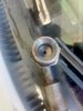
Are you 100% sure that the hose in the photo is both genuine and original..?That's pump outlet horse pipe fitted with an orifice. What's the function of orifice on pump outlet?
If yes, my bet is that it's an engineering "bodge" by the equipment manufacturer's engineers to get the pump to do something that the pump manufacturer did not design it to do. My opinion, others may differ.
Looks like not genuine because it is only 1 foot and installed at the centre of main pipeAre you 100% sure that the hose in the photo is both genuine and original..?
If yes, my bet is that it's an engineering "bodge" by the equipment manufacturer's engineers to get the pump to do something that the pump manufacturer did not design it to do. My opinion, others may differ.
The load sense compensator requires a pressure differential between pump outlet and load sense compensator to function properly. But isn't this orifice provided in load sense control valves?I've seen orifices like that in load sense lines. I wouldn't think that line is an output but would have to see the schematic again to be sure. Where does the hose go to?
John C.
Senior Member
In all the variable displacement systems I've worked on there are a few control pressures used as references. Springs in the regulators are the first controls and set the base level of control. Pump outlet pressure, many times internally sensed from internal porting but also may be crudely connected just by an external pipe or hose back to a fitting on the regulator is a second control type. That plus spring pressure is the basis for pump control. The next one or two depend on if the system is open center load sensing or closed center load sensing. Open center load sensing uses two hoses and an orifice plus a regulator in the main control valve while a closed center system uses a single hose from the main control valve that gets its pressure from some kind of manifold that connects all the function outputs. Your system might even be pressure compensated control with no load sensing. Basically the operating pressure in the system acts on the pump regulators and backs off flow as the pressure rises in the system. Where on the pump does the hose with the small orifice connect? Where on the control valve does it connect? It is very possible that it is the wrong hose completely. It would be fun to figure out your system with my hands on it but unfortunately my hands and arms can't reach you from here.
My pump has both compensator and load sense control with closed centre directional valves with ls circuits. What you see on the picture is an orifice on the main pump outlet that feeds the directional valve and it seems out of place.In all the variable displacement systems I've worked on there are a few control pressures used as references. Springs in the regulators are the first controls and set the base level of control. Pump outlet pressure, many times internally sensed from internal porting but also may be crudely connected just by an external pipe or hose back to a fitting on the regulator is a second control type. That plus spring pressure is the basis for pump control. The next one or two depend on if the system is open center load sensing or closed center load sensing. Open center load sensing uses two hoses and an orifice plus a regulator in the main control valve while a closed center system uses a single hose from the main control valve that gets its pressure from some kind of manifold that connects all the function outputs. Your system might even be pressure compensated control with no load sensing. Basically the operating pressure in the system acts on the pump regulators and backs off flow as the pressure rises in the system. Where on the pump does the hose with the small orifice connect? Where on the control valve does it connect? It is very possible that it is the wrong hose completely. It would be fun to figure out your system with my hands on it but unfortunately my hands and arms can't reach you from here.
Tinkerer
Senior Member
It is beginning to look like there is more than one piece to the puzzle of his pump failures.
Is it possible that the hose was mistakenly switched with the correct one while all those pump replacements were being done ?
Is it possible that the hose was mistakenly switched with the correct one while all those pump replacements were being done ?