crazydane
Well-Known Member
I received the AIM hydraulic quick coupler kit last week, and spent the weekend getting the hoses routed into the hydraulic area of the machine.
I installed the valve/solenoid in the front corner as seen here:
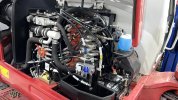
Blue marked hose goes to the lock side of the cylinder and the yellow goes to the release side. You can also see the short hose with the green mark on it going to the tank. I need to drain the tank before I can make that connection since the fluid will pour out if I remove the plug now. Ask me how I know, lol.
Anyway, looking at the instructions:
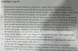
Per the service manual, the top 3 ports on the valve stack feeds the Bucket, Boom and Right travel motors. And it looks like this is the line from the pump that feeds those top 3 valves:
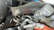
I need to Tee in this hose at that point I think:
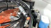
Note that it has a restrictor attached to prevent shock.
The Tees that came with the kit are kind of universal and none are the right ones for what I need.
I'm thinking my best bet is to to remove that hose coming from the pump and then remove the adapter the hose end screws into and figure out what I'm dealing with. I'm guessing 1/2" BSPP, so I think I need a Tee with 1/2" male and female BSPP and then a 1/4" JIC male.
Does that sound right? Also, I don't suppose there's another place on the valve block I can tab into more easily.
From the instructions, they are saying to use the test port on the pump, but the pump is in the opposite side of the machine from where the coupler valve is installed, so I would much prefer to tab into something closer.
And given that constant pressure is supplied to the coupler cylinder, I don't know that it matters which pump I tab into for pressure, since they have pressure when the engine is running, right?
I installed the valve/solenoid in the front corner as seen here:

Blue marked hose goes to the lock side of the cylinder and the yellow goes to the release side. You can also see the short hose with the green mark on it going to the tank. I need to drain the tank before I can make that connection since the fluid will pour out if I remove the plug now. Ask me how I know, lol.
Anyway, looking at the instructions:

Per the service manual, the top 3 ports on the valve stack feeds the Bucket, Boom and Right travel motors. And it looks like this is the line from the pump that feeds those top 3 valves:

I need to Tee in this hose at that point I think:

Note that it has a restrictor attached to prevent shock.
The Tees that came with the kit are kind of universal and none are the right ones for what I need.
I'm thinking my best bet is to to remove that hose coming from the pump and then remove the adapter the hose end screws into and figure out what I'm dealing with. I'm guessing 1/2" BSPP, so I think I need a Tee with 1/2" male and female BSPP and then a 1/4" JIC male.
Does that sound right? Also, I don't suppose there's another place on the valve block I can tab into more easily.
From the instructions, they are saying to use the test port on the pump, but the pump is in the opposite side of the machine from where the coupler valve is installed, so I would much prefer to tab into something closer.
And given that constant pressure is supplied to the coupler cylinder, I don't know that it matters which pump I tab into for pressure, since they have pressure when the engine is running, right?


