• Thank you for visiting HeavyEquipmentForums.com! Our objective is to provide industry professionals a place to gather to exchange questions, answers and ideas. We welcome you to register using the "Register" icon at the top of the page. We'd appreciate any help you can offer in spreading the word of our new site. The more members that join, the bigger resource for all to enjoy. Thank you!

Shredder Hydraulic Pump

John C.

Senior Member
Joined
Jun 11, 2007
Messages
12,870
Location
Northwest
Occupation
Machinery & Equipment Appraiser
Hi All,
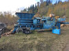
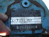
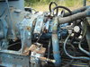
I'm working on a Eidal shredder that has a Rex Roth axial piston hydraulic pump in a closed loop system that need some attention. It is a two pump system and one pump isn't putting out the same as the other. The slow pump had a repair done on it last winter and the machine had not been used since. Another company did the repair and basically is trying to wash their hands of the project and the customer called me to try to get the machine to work again. At any rate I'm looking for information on the pump control system to see if the flow can be adjusted. I have included a photo of the ID tag on the pump. The Rex Roth distributor is of no use and they only want to work on it themselves and will supply no information outside of selling a new pump. Any information provided will be greatly appreciated.
Thanks
 

Attachments

  • DSC02317.JPG
    DSC02317.JPG
    609 KB · Views: 12

John C.

Senior Member
Joined
Jun 11, 2007
Messages
12,870
Location
Northwest
Occupation
Machinery & Equipment Appraiser
I do have a photo of the working pump.
 

Attachments

  • DSC02334.JPG
    DSC02334.JPG
    554.9 KB · Views: 30

mikebramel

Senior Member
Joined
Jul 15, 2012
Messages
1,612
Location
milwaukee
Check the charge pressure is the same for both units. That is also used as the control pressure. Directed by your coils up top to the ends of the control spool housing up top. Also if the opposing side of the spool is pressurized you won't get full stroke

Don't know what your tag codes out to but it looks like an A4.

You are saying they have 2 of the same pump, for two separate circuits.
 

John C.

Senior Member
Joined
Jun 11, 2007
Messages
12,870
Location
Northwest
Occupation
Machinery & Equipment Appraiser
Check the charge pressure is the same for both units. That is also used as the control pressure. Directed by your coils up top to the ends of the control spool housing up top. Also if the opposing side of the spool is pressurized you won't get full stroke

Don't know what your tag codes out to but it looks like an A4.

You are saying they have 2 of the same pump, for two separate circuits.

Thanks for the link and instruction book. It looks the same as my subject pump. There are four gauges already installed. Two for main pressure and two that appear to be plugged into the drain ports of each pump. I'll have to check that. The coils do work but I can't manually stroke the pump by pushing on the buttons in the ends of the spools. I figured there might be pilot pressure centering the servo control preventing me from moving them. It was the same on both pumps.

There is a pump for each rotor on the shredder. Both are driven from a multi-drive with a main clutch between the drive and the engine. Each pump is a closed loop system. There are pressure switches installed to stop and reverse the direction of the rotors when too big of load is applied. I have to try to figure out if the pressure switches are normally open or normally closed as well. I don't think that maters at this point as the slow rotor barely moves even at higher engine rpm.

Thanks again for the info and I'll let you know what I find.
 

TVA

Senior Member
Joined
May 14, 2018
Messages
2,245
Location
USA
Closed loop first and foremost is - charge pressure!
Then first keep it KISS, it’s been repaired, sonvisually check if displacement limiters have the same stick out length on both pump - you never know!
Then how do you know if this one is not putting as much as the other, did you actually flow tested both under pressure with analizer? In closed loop there’s always two - pump and motor!
Anything can happen, I’m actually finished working on skid steer not long ago were traction motor was replaced because the last time the traction motor failed, so when the other side stopped working the owner had no doubts - it had to be another traction motor, right? Well he had $5000 surprise!
Another thing about hydrostatics it is closed loop! Meaning not all the Oil gets flushed out by loop flashing circuit! And if the pump threw whole bunch of crap in to the loop it has very high probability of damaging the motor.

My friend gave me very good advise once how to check the charge pressure on the closed loop pump to save time: start right at the system port! But it must be in full neutral, at neutral shuttle valve is in middle position and your low and high side connected and read the same - charge pressure. Use high pressure digital gauge just in case the null on the pump is off ( I actually killed my bourbon tube gauge this way). If your charge pressure checked out there no need to check charge relief, charge filter etc.

Closed loop pump cannot be be judged by case drain flow - but I think you already know that, just a friendly reminder ;)!
 

TVA

Senior Member
Joined
May 14, 2018
Messages
2,245
Location
USA
Few more points: compare servo pressures of both pumps, you never know quality of “repair” could have just replace rotational group and didn’t bother to check servo!
And one thing I forgot you should check first - see if it is equipped with BYPASS valve, and if it in bypass position, then check system relief valves on both ports, and on both pump and motor.
 

TVA

Senior Member
Joined
May 14, 2018
Messages
2,245
Location
USA
Always wondered: why use expensive variable displacement pumps on shredders?!
Do they really adjust the speed on them? Isn’t it either ON or OFF? You can always back up with directional control valves it gets stuck!
 

John C.

Senior Member
Joined
Jun 11, 2007
Messages
12,870
Location
Northwest
Occupation
Machinery & Equipment Appraiser
mikebramel, I'll check that out when I get back to the machine. Thanks for the file and advise.
 

John C.

Senior Member
Joined
Jun 11, 2007
Messages
12,870
Location
Northwest
Occupation
Machinery & Equipment Appraiser
TVA, I would have answered your post but it was late last night.

The repair on the pump involved replacing the outside casing. It had a crack and was leaking. I have no information of what might have caused the crack and can only surmise that it was a bad casting in the first place. A quick look at the control components showed that the original paint on the locking nuts of the adjustment screws told me they had not been changed. The components were pulled off the casing in chunks and then reinstalled on the new casing.

I can tell the pump is not putting out because the rotor that it drives is barely turning while the other rotor driven by the other pump is spinning at nearly five times the rate. If you look at the photo of the pump you will see a pressure gauge installed on the working pump and there was also one on the non working pump. The working pump pressure at idle showed about five hundred PSI while the non working unit barely made 100 PSI. It that point I didn't need the use of a flow meter to tell me the pump was not putting out.

As to the motor being a possible issue, the owner told me the machine was working properly when they pulled the pump and did not work correctly when they installed it back in the machine. Symptoms didn't indicate a motor problem then, so are ruled out for the time being. If the rotor drive motor is bad I would suspect there would have been a lot of pressure with little flow or a lot of flow with associated noise to go with it when the rotor is turning. Neither of which is indicated.

If you had read my first post you might have made note that I asked for information on the pump control system. Before you can troubleshoot any system, whether it be hydraulic, electric, mechanical or smoke; you need to know how it is supposed to work. In my case, I identify the components in the system, investigate their operating principles and assess how they fit into the system and how their operation will affect the system performance. In this case I can see the pump is definitely not achieving the prescribed flow which is observed by the rotational speed of the rotor. Since the circuit is closed, the flow can't go anywhere else, hence it is not being generated in the first place. "KISS". If I find out the parameters of the control system of the pump I might be able to adjust it to correct the issue and save the owner a bunch of money. If not the owner will have the evidence necessary to go back to the people who accomplished the initial repair work and get some of his money back, or not. At that point I have identified the actual cost of repairing the machine so the owner can make a decision on whether to proceed any further.
 

TVA

Senior Member
Joined
May 14, 2018
Messages
2,245
Location
USA
TVA, I would have answered your post but it was late last night.

The repair on the pump involved replacing the outside casing. It had a crack and was leaking. I have no information of what might have caused the crack and can only surmise that it was a bad casting in the first place. A quick look at the control components showed that the original paint on the locking nuts of the adjustment screws told me they had not been changed. The components were pulled off the casing in chunks and then reinstalled on the new casing.

I can tell the pump is not putting out because the rotor that it drives is barely turning while the other rotor driven by the other pump is spinning at nearly five times the rate. If you look at the photo of the pump you will see a pressure gauge installed on the working pump and there was also one on the non working pump. The working pump pressure at idle showed about five hundred PSI while the non working unit barely made 100 PSI. It that point I didn't need the use of a flow meter to tell me the pump was not putting out.

As to the motor being a possible issue, the owner told me the machine was working properly when they pulled the pump and did not work correctly when they installed it back in the machine. Symptoms didn't indicate a motor problem then, so are ruled out for the time being. If the rotor drive motor is bad I would suspect there would have been a lot of pressure with little flow or a lot of flow with associated noise to go with it when the rotor is turning. Neither of which is indicated.

If you had read my first post you might have made note that I asked for information on the pump control system. Before you can troubleshoot any system, whether it be hydraulic, electric, mechanical or smoke; you need to know how it is supposed to work. In my case, I identify the components in the system, investigate their operating principles and assess how they fit into the system and how their operation will affect the system performance. In this case I can see the pump is definitely not achieving the prescribed flow which is observed by the rotational speed of the rotor. Since the circuit is closed, the flow can't go anywhere else, hence it is not being generated in the first place. "KISS". If I find out the parameters of the control system of the pump I might be able to adjust it to correct the issue and save the owner a bunch of money. If not the owner will have the evidence necessary to go back to the people who accomplished the initial repair work and get some of his money back, or not. At that point I have identified the actual cost of repairing the machine so the owner can make a decision on whether to proceed any further.

Working pressure at idle, I assume is the neutral position, and engine running IS your charge pressure! under one condition - correctly set null. I would check that one first! If pumps use mutual charge filter check the charge relief pressure! If not got to do the whole enchilada, can’t see from pictures if each pump has its own charge pump or mutual one.

That’s why these pumps have gauges installed in the case drain, high case pressure can not only push the seals out but crack the case it self.

Sorry John I was kinda busy yesterday so I decided to dump the list of problems on you! Kind of a check list to go by.
Closed loop is finnicky ones - I had to learn that the hard way, thank God I had good help!
 

TVA

Senior Member
Joined
May 14, 2018
Messages
2,245
Location
USA
TVA, I would have answered your post but it was late last night.

The repair on the pump involved replacing the outside casing. It had a crack and was leaking. I have no information of what might have caused the crack and can only surmise that it was a bad casting in the first place. A quick look at the control components showed that the original paint on the locking nuts of the adjustment screws told me they had not been changed. The components were pulled off the casing in chunks and then reinstalled on the new casing.

I can tell the pump is not putting out because the rotor that it drives is barely turning while the other rotor driven by the other pump is spinning at nearly five times the rate. If you look at the photo of the pump you will see a pressure gauge installed on the working pump and there was also one on the non working pump. The working pump pressure at idle showed about five hundred PSI while the non working unit barely made 100 PSI. It that point I didn't need the use of a flow meter to tell me the pump was not putting out.

As to the motor being a possible issue, the owner told me the machine was working properly when they pulled the pump and did not work correctly when they installed it back in the machine. Symptoms didn't indicate a motor problem then, so are ruled out for the time being. If the rotor drive motor is bad I would suspect there would have been a lot of pressure with little flow or a lot of flow with associated noise to go with it when the rotor is turning. Neither of which is indicated.

If you had read my first post you might have made note that I asked for information on the pump control system. Before you can troubleshoot any system, whether it be hydraulic, electric, mechanical or smoke; you need to know how it is supposed to work. In my case, I identify the components in the system, investigate their operating principles and assess how they fit into the system and how their operation will affect the system performance. In this case I can see the pump is definitely not achieving the prescribed flow which is observed by the rotational speed of the rotor. Since the circuit is closed, the flow can't go anywhere else, hence it is not being generated in the first place. "KISS". If I find out the parameters of the control system of the pump I might be able to adjust it to correct the issue and save the owner a bunch of money. If not the owner will have the evidence necessary to go back to the people who accomplished the initial repair work and get some of his money back, or not. At that point I have identified the actual cost of repairing the machine so the owner can make a decision on whether to proceed any further.

At idle did you mean with rotor running but nothing to shred? If it what you meant than forget everything I said earlier!

Did you find the way to check servo pressure?
 
Last edited:

TVA

Senior Member
Joined
May 14, 2018
Messages
2,245
Location
USA
But don’t forget about bypass valve!

Never dealt with these on shredders, but on vehicles - if pump in good condition at , full flow sometimes it can creep. They we’re not designed to tow vehicles at high speeds, just can’t pass so much flow through!
 
Last edited:

John C.

Senior Member
Joined
Jun 11, 2007
Messages
12,870
Location
Northwest
Occupation
Machinery & Equipment Appraiser
Found the right distributor on Friday who put me in touch with their rebuilder. Valin is the distributor out here now and the gentleman provide a ton of insight. He called the pump a model 125 and said the only thing Rex Roth was the outside casing. Parts are rare but they have saved parts from damaged pumps over time and he figures they could repair it pretty easy if it can't be adjusted. He sent me the photos showing the porting on the pump and the schematic for the control system. Hopefully I can get back to the machine tomorrow and get the pump working properly. I'll let you know what I find.
 

John C.

Senior Member
Joined
Jun 11, 2007
Messages
12,870
Location
Northwest
Occupation
Machinery & Equipment Appraiser
Got back to the machine today and got some answers. First of all the pumps are AA4V125 units built in 1992. The identified problem with the problem pump is charge pressure. It only make about 200 when the pumps are spun and drops off to about a hundred within thirty seconds. I checked with the rebuilder in Portland asking if there was anyway the oil could be routed some place other than where it's supposed to go and he said yes. There are a couple of make up check valves that could be stuck so I'm headed back there tomorrow to pull those. If that don't fix it the owner wants to pull the pump and send it in for teardown and repair. I've taken some photos of the machine for general interest.

IMG_0604.jpg IMG_0604.jpg IMG_0605.jpg IMG_0607.jpg
 

Attachments

  • IMG_0606.jpg
    IMG_0606.jpg
    384.6 KB · Views: 0

hosspuller

Senior Member
Joined
Aug 27, 2014
Messages
1,872
Location
North Carolina
John C … Do the pumps turn in the same direction or is one CW while the other CCW ? Had a machine with poor output, reversed the rotation and Bing-go ! (three phase motor, direction not easily visible) Perhaps the folks that rebuilt the pump set it for wrong rotation or wrong case for rotation direction.
 
Top