
-
Thank you for visiting HeavyEquipmentForums.com! Our objective is to provide industry professionals a place to gather to exchange questions, answers and ideas. We welcome you to register using the "Register" icon at the top of the page. We'd appreciate any help you can offer in spreading the word of our new site. The more members that join, the bigger resource for all to enjoy. Thank you!
You are using an out of date browser. It may not display this or other websites correctly.
You should upgrade or use an alternative browser.
You should upgrade or use an alternative browser.
Series 60 ddec2 wiring diagram
- Thread starter workshoprat92
- Start date
workshoprat92
Senior Member
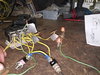
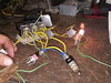
Unfortunatly im working with one of those harnesses that does not have wire colors but all wires are white lol. Some wires have readable numbers some are trace em down kinda operation. Yesterday i went wire by wire completly through my interface harness and identified and labled every wire.Try it out with lights first that will definitely tell you if diodes are needed to stop any backfeed.
Looking at one schematic it doesn't show numbers for the Jake wires in the head. It gives a red wire as activating two solenoids and a blue wire for the remaining center cylinder. I hope that helps.
This morning i got my circuit powered up and everything works perfectly. I have no feedback and i do not see a need for diodes. Makes me think i designed a better or simpler circuit than what factory had. Hard to believe but it seems to work at least on the bench in theory!
Attachments

workshoprat92
Senior Member

workshoprat92
Senior Member
Hey thats a great diagram. Ok yea i can see the diode now to protect ecm. That makes sense. Wish i knew what size to get lol. Also something else i see the jake on switch is double pole and it also opens the ecm relay control circuit in off mode and that makes sense so its not neddlesly working the relay and that also keeps that circuit from being on for long periods of time. Its probably not a 100% duty cycle circuit at the ecm level.
Birken Vogt
Charter Member
These have a very convenient package, 6 amps IIRC. Is that enough for your application?
http://www.partsfortechs.com/asapcart/kohler-233959-rectifer-diode-replaces-241739-p-509.html
http://www.partsfortechs.com/asapcart/kohler-233959-rectifer-diode-replaces-241739-p-509.html
workshoprat92
Senior Member
Yea thats pretty cool it has the spade connectors. I dont know why it wouldnt work!These have a very convenient package, 6 amps IIRC. Is that enough for your application?
http://www.partsfortechs.com/asapcart/kohler-233959-rectifer-diode-replaces-241739-p-509.html
workshoprat92
Senior Member
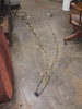
Making more progress. Got a radiator hung today out of an old 70s cabover international. Just gotta hook it all up. Gotta love the shutter stats! Why did the ever get rid of those? They were fantastic!
workshoprat92
Senior Member
Making more progress. Got a radiator hung today out of an old 70s cabover international. Just gotta hook it all up. Gotta love the shutter stats! Why did they ever get rid of those? They were fantastic! Getting closer to being able to fire this ol girl up! Working on this while im.waiting for switches and other parts to show up from amazon!
ever get rid of those? They were fantastic! Getting closer to being able to fire this ol girl up! Working on this while im.waiting for switches and other parts to show up from amazon!Birken Vogt
Charter Member
Of course the answer why they can't have shutters today is that aftercoolers and condensers need full air flow at all times. Those huge hazmat placards can block a lot of air. Move them to the bumper and the fan runs a lot less.
How did the shutters work in that case? How did they interact with the thermostat?
How did the shutters work in that case? How did they interact with the thermostat?
workshoprat92
Senior Member
There was a thermostat control valve on the engine that sensed engine temp and would apply air to open or close depending on temp. They also had a cylinder in the air conditioning hoses that wouls open them when the air conditioner was on. They really were a great system!Of course the answer why they can't have shutters today is that aftercoolers and condensers need full air flow at all times. Those huge hazmat placards can block a lot of air. Move them to the bumper and the fan runs a lot less.
How did the shutters work in that case? How did they interact with the thermostat?
workshoprat92
Senior Member
RZucker
Senior Member
You should be able to short the coolant sensor plug and keep it happy.
workshoprat92
Senior Member
So basically ground out the wire from the ecm? Or do you mean the plug from the coolang level module? I dont have a module but they are pretty cheap on ebay.You should be able to short the coolant sensor plug and keep it happy.
RZucker
Senior Member
Just a paper clip across the plug terminals.
workshoprat92
Senior Member
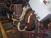
Got this engine started on the engine stand today! Only thing is it wont throttle up. From every thing i can see i have it wired correctly. I have checked continuity and checked how i have it wired to the interface harness connector location several times. I can hook my pro link in and it shows tps cnts moves when you run the throttle. The tps pct does nothing and just reads 0%. I have got to think at this point something in the ecm is keeping it from throttling up. Anything i should check?
workshoprat92
Senior Member
Also my high idle does not work and it keeps flashing code 25 which is no codes present. Even when running it keeps flashing that. Shouldnt that quit flashing once running?
I do not have a vss or coolant level sensor and module wired in. Could that be a reason it wont throttle?
I do not have a vss or coolant level sensor and module wired in. Could that be a reason it wont throttle?
workshoprat92
Senior Member
Ok got my cruise to work. Figured out my clutch and brake switch was wired backwards. Not sure how I did that. Anyhow i now have high idle and can throttle it with the cruise switches. Still not with throttle pedal. Will switch the wires the right way but i doubt that will solve the throttle peddle issue!