• Thank you for visiting HeavyEquipmentForums.com! Our objective is to provide industry professionals a place to gather to exchange questions, answers and ideas. We welcome you to register using the "Register" icon at the top of the page. We'd appreciate any help you can offer in spreading the word of our new site. The more members that join, the bigger resource for all to enjoy. Thank you!

Pump to engine coupler

T_Gunn

Active Member
Joined
Jan 11, 2009
Messages
37
Location
Nova Scotia
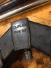
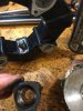
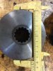
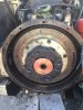
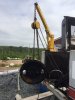
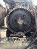
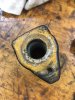
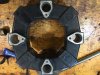
So I removed the pump assembly on my 1991 Linkbelt LS2700C2 to have some hydraulic leaks fixed. When I remove the pump housing it was immediately obvious what had been clunking every time I shut the machine off. (see picture of engine drive plate and coupler 'fingers') After a great deal of internet research and calls to my Linkbelt and Case dealers (this Linkbelt is also a Case 9020 with a Cummins 4bt instead of an Isuzu 4BD1T) I learned that parts are getting very difficult to get for my 25 year old machine. So long story short, I ended up buying a new pump coupler on Ebay, which is advertised as being for a JCB JS150 machine, which I learned is a UK version of the same machine. The part no's for the coupler are the same. After receiving the JCB coupler, and starting to install it, I now realize that it is a bit of a generic piece that fits a lot of excavators. If you look at my picture of the coupler, you can see that the bore holes that bolt to the drive plate/flywheel size on the engine side of the coupler are machined through holes of the same size. The head of the allen head bolts that bolts the coupler to the engine plate is smaller than the bore hole so that the bolt head will sit below the surface of the coupler when installed. But...there is no step in the bolt hole to tighten the bolt and coupler to the drive plate. When I looked more closely at the original worn out drive 'finger', it appears that there is a bushing pressed into the finger (see picture). This bushing would be what the allen bolt tightens on to clamp the coupler to the drive plate. So...I tried to press this bushing out of the finger with a 6 ton jack and it won't budge. My question is... is this actually a bushing that can be pressed out, I just need more than 6 tons of force? Would I be better off to source a new set of bushings that need to be installed in the new coupler piece? Is a press fitted bushing going to be enough to keep the coupler from moving away from the drive plate over time?, as it will be the only thing actually holding the coupler against the drive plate?
Hope I am making sense. Any help would be welcome.
 

Attachments

  • IMG_5402.JPG
    IMG_5402.JPG
    62.5 KB · Views: 250
  • IMG_5406.JPG
    IMG_5406.JPG
    78 KB · Views: 245
  • IMG_6002.JPG
    IMG_6002.JPG
    61.8 KB · Views: 256
  • IMG_6004.JPG
    IMG_6004.JPG
    74.9 KB · Views: 248

willie59

Administrator
Joined
Dec 21, 2008
Messages
13,388
Location
Knoxville TN
Occupation
Service Manager
Yes, you could call that a bushing (for lack of better term) inside that "finger" as you called it, but it's not pressed in, not pressed fit, it's actually supposed to be "slip" fit, the problem is that bushing is seized in your old fingers. The way it's supposed to work, let's go through the install procedure...

You should have a round/splined hub that fits on the pump shaft, the splined hub is split with allen head pinching bolts, when you slip the splined hub on the pump shaft and locate it in the proper fore/aft position, you clamp it tight to the pump shaft with the allen head pinching bolts.

Next, you fit the rubber coupler onto the splined shaft hub and fasten it to the hub with the four allen head bolts.

Lastly, those "seized bushings" should actually simply be mount bushings that are attached to the flywheel with allen head bolt, no fingers fitted onto them, basically just 4 big studs sticking off of the flywheel. Lift the assembled pump and drive, move it into position and align the holes in the flex drive with the "studs" sticking off of the flywheel. Once you get the two mated...drive it home.

That's the way it's supposed to work.

Oh, and you learned something all by yourself that most folks don't recognize...anytime you hear clunk clunk clunk when you shut the engine down, the flex coupler has gone south. :)
 
Last edited:

willie59

Administrator
Joined
Dec 21, 2008
Messages
13,388
Location
Knoxville TN
Occupation
Service Manager
BTW, those fingers (or T blocks, whatever we choose to call them) are aluminum whereas the bushings are steel. Moisture, dissimilar metals = oxidation. Whether it's rust on steel, or corrosion on aluminum, oxidation is Gods Locktite. You might be able to heat those aluminum T blocks a bit, break that corrosion bond and drive those bushing out. Clean the bushings up good and re-use them. Put the silver snot on them and the bores of the new coupler on re-assembly. I've always said, if it doesn't get Locktite...it gets Never Seize.
 

T_Gunn

Active Member
Joined
Jan 11, 2009
Messages
37
Location
Nova Scotia
Ok, very interesting,when I removed the splined hub, it was floating freely on the splined pump shaft. I assumed that the assembly was held in place from the engine side because the 'fingers' and studs were stuck together. I will look at it again from this new perspective. Is there any hope of separating the 'bushings' from the fingers? They look like Aluminum that has galled. I might be better off to see if I can buy some 25mm bushings and make new studs for the drive plate. Thanks for this. I have the service manual for the machine but it sure doesn't go into this level of detail!
 

willie59

Administrator
Joined
Dec 21, 2008
Messages
13,388
Location
Knoxville TN
Occupation
Service Manager
I've never had them that stuck, but again, those V blocks are aluminum, low melting point, whereas the bushings are steel. They're mounted on the flywheel in the pic. Put some heat to the T blocks with a torch and start peening them with a hammer, they'll probably shake loose at some point.
 

willie59

Administrator
Joined
Dec 21, 2008
Messages
13,388
Location
Knoxville TN
Occupation
Service Manager
Another option, remove the V blocks from the flywheel. Take a zizz wheel and cut a slit down opposing sides of the aluminum V blocks, split them from the bushings.
 

lantraxco

Senior Member
Joined
Jan 1, 2009
Messages
7,704
Location
Elsewhen
Willie, I have to politely disagree, for splined hubs it's a different setup, no bushings in there, it's solid aluminum.

That's the wrong rubber coupler, that's the slip version, you need the bolt version which is used with slip fit spline couplings.

Should be a number on the coupler molded in for size, or measure the OD of the center hub I can identify it for you.

140AS.jpg
 

T_Gunn

Active Member
Joined
Jan 11, 2009
Messages
37
Location
Nova Scotia
I will take some measurements tonight and post. There was no number molded on the coupler as there was not rubber left.
 

lantraxco

Senior Member
Joined
Jan 1, 2009
Messages
7,704
Location
Elsewhen
I will take some measurements tonight and post. There was no number molded on the coupler as there was not rubber left.

I meant the new one you have there, assuming it's the right size but just the wrong type, though anything is possible.
 

willie59

Administrator
Joined
Dec 21, 2008
Messages
13,388
Location
Knoxville TN
Occupation
Service Manager
Willie, I have to politely disagree, for splined hubs it's a different setup, no bushings in there, it's solid aluminum.

That's the wrong rubber coupler, that's the slip version, you need the bolt version which is used with slip fit spline coupling

Nice catch lantraxco, I had totally forgot there were two types of couplers, and I think you're absolutely right, that's the wrong coupler. Now that I think about it, the new coupler T_Gunn has there "is" made to slip onto studs on the flywheel. But if I recall correctly, those studs on those couplers aren't allen head bolts, they're actually an allen head stud. Been a while since I've worked on one though so I'm not at all certain. :)
 

T_Gunn

Active Member
Joined
Jan 11, 2009
Messages
37
Location
Nova Scotia
Took some measurements and pics. Splined coupler is 100 mm in dia. The holes in the splined coupler are blind and cannot be screwed in to clamp onto the splined pump shaft. Thanks to lantraxco for jumping in. Coupler appears to be size 50 and the bolt holes were a good fit to the splined coupling and the drive plate with the exception of the now more clearly understood problems. Not sure where to go from here.
 

Attachments

  • IMG_6011.JPG
    IMG_6011.JPG
    49.4 KB · Views: 168
  • IMG_6015.JPG
    IMG_6015.JPG
    65.5 KB · Views: 167
  • IMG_6009.JPG
    IMG_6009.JPG
    68.4 KB · Views: 165

lantraxco

Senior Member
Joined
Jan 1, 2009
Messages
7,704
Location
Elsewhen
Okay, if the old aluminum pieces are of the same length (width?) as that new 50 coupler, it's a 50, could also be an 80 with a 100mm OD hub, but the 80 is 65mm thick where the 50 is only 58. Not a huge difference.

I would suggest checking with whoever you got that coupler from (assuming it's not overseas) and see if they have the correct type, or if they'll at least refund your money since it isn't correct.

I'm not trolling for business, but as it happens the Morooka 800VD uses the exact same coupler donut (the earlier 800 uses the slip version with dowel studs) so if you need one, I got some, and if you can't return that one I might be persuaded to take it in trade as I can put it on the shelf next to the ones I stock here.

50AS coupler 002.jpg

50AS coupler 003.jpg

50AS coupler 005.jpg
 

lantraxco

Senior Member
Joined
Jan 1, 2009
Messages
7,704
Location
Elsewhen
Nice catch lantraxco, I had totally forgot there were two types of couplers, and I think you're absolutely right, that's the wrong coupler. Now that I think about it, the new coupler T_Gunn has there "is" made to slip onto studs on the flywheel. But if I recall correctly, those studs on those couplers aren't allen head bolts, they're actually an allen head stud. Been a while since I've worked on one though so I'm not at all certain. :)

There's so many variations on these, along with the hard white plastic blocks and aluminum anchors type, etc. it's no wonder we can't keep track. The Morookas use them both ways, depending on whether the pump shaft is tapered and keyed or splined. Then there's the setup where they use a "Centalock" hub that locks to the splines and your back to the coupler that slips over the dowel pins, but that's not Morooka at least that I know of! LOL
 

lantraxco

Senior Member
Joined
Jan 1, 2009
Messages
7,704
Location
Elsewhen
Oh, just a random thought since it hit my addled brain, T_Gunn mentioned there was no rubber left in there.... whose bright idea was it to make these flex couplers out of a rubber material that turns to jelly when a little bit of oil or fuel hits it? :eek:
 

T_Gunn

Active Member
Joined
Jan 11, 2009
Messages
37
Location
Nova Scotia
An update. I contacted the Ebay seller and explained my problem. He recognized immediately that the coupler he had sent was the wrong one (picked from the wrong shelf) and has shipped me the proper one. I will provide more information when I have received the new piece.
 

T_Gunn

Active Member
Joined
Jan 11, 2009
Messages
37
Location
Nova Scotia
Another update. I have recieved and installed new coupler. Seems to be a good fit. Between that and the new motor mounts I installed too, the machine has never run so smoothly while I owned it. Many thanks to lantraxco and willie59.
 

Attachments

  • IMG_6085.JPG
    IMG_6085.JPG
    73.3 KB · Views: 63

willie59

Administrator
Joined
Dec 21, 2008
Messages
13,388
Location
Knoxville TN
Occupation
Service Manager
Looks good indeed! And it's good you got it sorted out without having to pay a road mechanic to do the job. :drinkup
 
Top