willie59
Administrator
Just trying to educate myself and get a better understanding of how the system works..
Which is exactly the way you do it roddy, kudos for your curiosity. :drinkup

Just trying to educate myself and get a better understanding of how the system works..
Even better would be to be able to set up a mapping program where you click on a line and it colors it all through the schematic.
")
Schematics are to help people troubleshoot and should be accurate. It wouldn't be the first time I've come across errors (even in Cat drawings


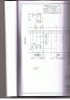
Guys, I found another oddity. This is the redundant parking brake solenoid valve on the full drawing. At first glance it looks like a closed center 4 way valve, but it's shown shifted to the end section, and it shows a spring on one end and a solenoid coil on the other end. In all my years of looking at diagrams I have never seen something drawn like thi
View attachment 111437
That is a two position valve with an "all ports blocked condition" as the spool transitions from one position to another. On some applications it won't matter, on others it will. Been on the receiving end of some bad engineering with an 'all ports blocked" condition where the rod gland would be blown. fortunately Rexroth offers the same two position valve with an "all ports open" condition.
Have a good day,
Maytag