• Thank you for visiting HeavyEquipmentForums.com! Our objective is to provide industry professionals a place to gather to exchange questions, answers and ideas. We welcome you to register using the "Register" icon at the top of the page. We'd appreciate any help you can offer in spreading the word of our new site. The more members that join, the bigger resource for all to enjoy. Thank you!

Mitsubishi mm30sr

Graham Hamilton

Active Member
Joined
Aug 18, 2019
Messages
31
Location
Scotland
Yeh I'll send what I have. They are also available on my web site https://www.woodandtrees.co.uk/

If the tracks and blade work, its something to do with the electrics/electronics. I've had this problem and it was a bad connection on the safety arm switch/relay connections. Below the seat there are two doors, the first one is the heater and safety arm switch, so check the switch connections. The second door holds 4 relays and a glow plug timer. The 3rd one away from you, Start Safety Relay, is connected to the safety arm. Yellow wire. Worth proving these connections with a resistance meter. It should click as you operate the safely arm but can be difficult to hear with the engine running so put your hand on it to feel it clicking. There is a wiring diagram for this in the MM50 manuals which I believe is the same as the MM30.
 

mick18

Member
Joined
Nov 15, 2023
Messages
7
Location
Canada
I have had the same problem. Have either of you fixed your problem yet? I have a copy of the Diagnostic Manual for the Electronic system for Mitsubishi MM30SR , MM40SR , MM55SR , MM55SR-2 These were translated from the original Japanese. Also have parts manual for MM30SR. Does anyone know how I could reach these guys? Thanks td6man
I it si possible to have the manuel ?
 

T-in-T

Member
Joined
Jan 2, 2011
Messages
12
Location
TN
If any function of the electric over hydraulic system fails, the whole electric control system stops. this could be from just a frayed lead going to the position potentiometers on the boom or corrosion in the connections, particularly ay the control box so check all these first.. But most likely it is from an out of whack joystick. A couple years ago I led a fellow from Russia through the diagnostic procedures and he figured out how to readjust the sensors and potentiometers in the joysticks. Those discussions with him are about 2-3 pages back (2020) in this forum. Suggest you read them and see if you can't follow them to determine if it is a joystick problem. There are test points in the control box and these past posts tell how to use them for diagnostics. Lots o' luck to you. But to hell with Putin and his forces in Ukraine.
 

mikolaj

New Member
Joined
Dec 6, 2023
Messages
2
Location
Russia
hi everybody. I'm having difficulty with the hydraulics on the mm55sr excavator. I was removing the battery to charge it. then he put it back in its place . I tried to start it . it didn 't start . I remembered that I had not connected the minus cable to the battery, without disconnecting the ignition switch, I connected the cable to the battery. after that, I started the excovator. but the electrical control is gone. the stroke and blade are working. I opened the computer . there is no indication of error diagnosis. there is only a row of yellow LEDs. they give flashes . at half brightness and at full brightness .error codes for the display that is located under the joystick . 0033 : 0052: 00A8: 00b6
 

mikolaj

New Member
Joined
Dec 6, 2023
Messages
2
Location
Russia
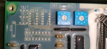
I also want to make a diagnosis in the computer. who can look and write which transistors tr15-tr17. as well as ra27-ra28. should be installed? and does it make sense? maybe the firmware does not provide an indication?IMG_20231207_183122.jpg
 

JDC21

Member
Joined
Feb 2, 2022
Messages
12
Location
NC
hi everybody. I'm having difficulty with the hydraulics on the mm55sr excavator. I was removing the battery to charge it. then he put it back in its place . I tried to start it . it didn 't start . I remembered that I had not connected the minus cable to the battery, without disconnecting the ignition switch, I connected the cable to the battery. after that, I started the excovator. but the electrical control is gone. the stroke and blade are working. I opened the computer . there is no indication of error diagnosis. there is only a row of yellow LEDs. they give flashes . at half brightness and at full brightness .error codes for the display that is located under the joystick . 0033 : 0052: 00A8: 00b6
I think the error diagnosis codes are being displayed on the display below the joystick. Graham Hamilton,s web site has a list of error codes. On page 277 of his info for the MM55SR at the bottom of page "error code B6 and A8 can be neglected". Page 275 code 33=swing in ,code 52=front/back of LH below 2.3 v
Maybe this will help
 

JDC21

Member
Joined
Feb 2, 2022
Messages
12
Location
NC
I also want to make a diagnosis in the computer. who can look and write which transistors tr15-tr17. as well as ra27-ra28. should be installed? and does it make sense? maybe the firmware does not provide an indication?View attachment 300235
The led modules 14, 15 would indicate error codes. Tr15-17 and resistors are associated with these leds.
Your error codes are being sent to the display below the joystick, I think.
 

mick18

Member
Joined
Nov 15, 2023
Messages
7
Location
Canada
I removed the original electronic system to install relocated proportional joysticks. I connected my joystick to the coils on top of the body valve. The joystick sends 0-12v to the coil but I have no proportional action on the coils. My functions are on off. The coil does not act proportionally. Is it the coil on the body valve that controls the functions or is it the block with 5 wires in the end of the spool?
1000003517.jpg
 

JDC21

Member
Joined
Feb 2, 2022
Messages
12
Location
NC
I removed the original electronic system to install relocated proportional joysticks. I connected my joystick to the coils on top of the body valve. The joystick sends 0-12v to the coil but I have no proportional action on the coils. My functions are on off. The coil does not act proportionally. Is it the coil on the body valve that controls the functions or is it the block with 5 wires in the end of the spool?
The block with the five wires is the lvdt feedback to let the electronics know how much the spool has moved and which direction. This feedback cancels out the demand going to the valve to keep it from saturating in the open or close/in or out.
 

mick18

Member
Joined
Nov 15, 2023
Messages
7
Location
Canada
The block with the five wires is the lvdt feedback to let the electronics know how much the spool has moved and which direction. This feedback cancels out the demand going to the valve to keep it from saturating in the open or close/in or out.
Ok and do you know if the original 10 coil on valve are proportionnal 0-12 v ?
 

JDC21

Member
Joined
Feb 2, 2022
Messages
12
Location
NC
If you have feedback, I would say they are not proportional. I am looking at the description of MM55SR solenoids, "using high response solenoids and differential transformer (lvdt)"
Why are you doing away with your electronic controls?
 

mick18

Member
Joined
Nov 15, 2023
Messages
7
Location
Canada
If you have feedback, I would say they are not proportional. I am looking at the description of MM55SR solenoids, "using high response solenoids and differential transformer (lvdt)"
Why are you doing away with your
If you have feedback, I would say they are not proportional. I am looking at the description of MM55SR solenoids, "using high response solenoids and differential transformer (lvdt)"
Why are you doing away with your electronic controls?
Because the previous owner had problems with the original joysticks and the modified system with on/off micro switches. It's really not pleasant to operate. I removed everything and relocated the adjustable proportional joystick. Do you have an electrical plan? Or a part number for the coils I can't find anything anywhere
 

JDC21

Member
Joined
Feb 2, 2022
Messages
12
Location
NC
Sorry, I am unable to help you on the "proportional hookup". Maybe others can help.
 

Graham Hamilton

Active Member
Joined
Aug 18, 2019
Messages
31
Location
Scotland
I'm not sure about this machine's solenoids and what signal they get .....but it's common for proportional solenoid valves to get a Pulse Width Modulation signal (PWM) from the controller. The 12Volts is pulsed many times per second. The longer the ON pulse the more power goes to the solenoid and the more it moves. If it's PWM you should see on your multimeter the "average" voltage change on the solenoid terminals as you move the joysticks. ie 0 to 12V swing.
The LVDT tells the controller where the spool is and I would have thought this signal would be used to adjust/trim the PWM to the solenoid as a feedback loop stopping it over shoot etc.
 

BDaechsel

New Member
Joined
May 9, 2023
Messages
3
Location
Alberta Canada
Looking for a parts place for a potentiometer mm30sr
The potentiometer on the stick and boom
Wires have been ripped out
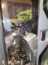
And was told I can’t spilt it to splice the wires IMG_1212.jpeg
 

Graham Hamilton

Active Member
Joined
Aug 18, 2019
Messages
31
Location
Scotland
I've never seen a MM30SR parts manual but I've attached the MM50 parts manual diagrams which might help. Part 12 (PA 4786) seems the potentiometer but I didn't find this on a web search.
There are parts suppliers in Japan which might help.
https://www.maxis.jp/ and https://japanmachineryparts.com/mitsubishi.

Australia is another country who seem to have Mitsubishi excavators. Found this company which might be of help.
https://excavatorparts.com.au/category/mitsubishi/

Let us know how you get on
 

Attachments

  • mm55sr Potentiometers.pdf
    69.7 KB · Views: 9
Top