• Thank you for visiting HeavyEquipmentForums.com! Our objective is to provide industry professionals a place to gather to exchange questions, answers and ideas. We welcome you to register using the "Register" icon at the top of the page. We'd appreciate any help you can offer in spreading the word of our new site. The more members that join, the bigger resource for all to enjoy. Thank you!

Komatsu PC75UU1 won't lift boom

NCMilt

Member
Joined
Apr 23, 2021
Messages
9
Location
North Carolina
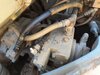
Call this a restoration project...
Suddenly, I can't raise the boom on its own nor move the bucket with any strength.
The boom budges, but won't lift. The bucket will move through most of its travel if it has no resistance.
Strangely, if I push the stick out, and pull up on the boom, it will raise, slowly, while the stick moves. Almost like I'm pumping it up with the stick..

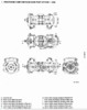
This machine has 3 valve blocks:
1 controls the blade.
The next controls bucket, boom, offset & right track. I can't load the offset to test its strength. It moves fine. That probably doesn't mean much. But the bucket, boom, and right track are very weak. Except when I operate something on the next valve block at the same time. Still weak, but much stronger.
The third controls left track, stick, and rotation. All these seem fine.

Why would operating valves on the 3rd block assist pistons attached to the 2nd?

What's wrong with my machine?
 

uffex

Senior Member
Joined
Jan 23, 2012
Messages
4,464
Location
Lincoln UK
Occupation
Admin
Good day NC
I only have a hydraulic schematic for the PC75-2 from the description yours is not the same if you have a hydraulic schematic to share may be able to work it out.
Kind regards
Uffex
 

NCMilt

Member
Joined
Apr 23, 2021
Messages
9
Location
North Carolina
And here is a screen shot of the hydraulic diagram for a PC75-UU1 (at least the manual says it is)
PC75UU1Hydraulics.PNG
 

John C.

Senior Member
Joined
Jun 11, 2007
Messages
12,870
Location
Northwest
Occupation
Machinery & Equipment Appraiser
Before doing anything else I would suggest checking the filter for debris. After that I would look at the hydraulic strainer in the tank looking for any signs of internal failures. Cylinder packing pieces and possibly brass or steel. If all that is clear you might consider an oil analysis of the hydraulic oil.

The schematic shows an open center parallel passage system with manual spool controls. It doesn't show any kind of straight travel function. The piston pumps are servo controlled. My first thought is that your machine would be considered old, time wise, so I would suspect the spools in the servo control of the rear pump might be stuck. That's why and fluid analysis would be considered. If the oil analysis shows OK and the spools in the servo are fine, then I would have to suspect the pump itself.

How many hours show on the meter?
 

uffex

Senior Member
Joined
Jan 23, 2012
Messages
4,464
Location
Lincoln UK
Occupation
Admin
Good day
According to the Hydraulic schematic the affected functions are all in the five spool section I guess one track is also without power. it appears that you are without pressure from that pump. If you have the possibility to switch the relief valve it would be what I would suggest to begin with.
Kind regards
Uffex
 

NCMilt

Member
Joined
Apr 23, 2021
Messages
9
Location
North Carolina
Uffex, you are correct about the affected functions being all on that valve block and therefore the rear pump. I replaced the relief valve due to other issues with a new one from Komatsu. Maybe I can adjust it, but it's probably not the relief valve. I really don't understand why I can move the boom if I move the stick at the same time. The bucket works the same way. But I don't think either are at full strength then, just enough to lift the boom.

John C, there is a straight travel function mentioned in the text of the manual and on the electrical diagram. But I don't understand what that implies. Does that somehow connect the two valve blocks together on one pump? Does operating one pump increase system pressure? I'm still mystified by the boom moving only when I move the stick (or rotate).

The machine is very old and very used. The hour meter doesn't work and didn't for the guy from whom I bought it. But it would be a high number. I did mention this is a restoration project.

I'm pretty good with electrical and electronic schematics. I don't know the symbols or labels for hydraulics, so I need to learn more about that.

I'm not in the same state with the machine right now. I'll be back near it midweek and I'll look at the screen & filter. Murphy's law tells me it's going to be the most difficult and expensive part, so it is probably the pump. But I need to prove that before I even think about pulling it.

Thanks for the advice. Keep it coming!
 

John C.

Senior Member
Joined
Jun 11, 2007
Messages
12,870
Location
Northwest
Occupation
Machinery & Equipment Appraiser
I looked through the schematic again and do see a straight travel valve in the five spool valve. It basically joins both pump flows together when you operate an implement while you are traveling. I also now see a second boom valve in the four valve body. My thoughts are that one pump is stroking up correctly while the other one lags for some reason. Both sets of pump controls are represented in the schematic with the pumps. There are three lines connecting both of the pump controllers. That's why I was thinking about a control piston stuck. I'm not sure of a way of checking the operation of those operationally. I haven't been into one of those pumps either, so I just using the logic of the schematic and pieces of experience.
 

NCMilt

Member
Joined
Apr 23, 2021
Messages
9
Location
North Carolina
So, what triggers the servo to enable the main pump? This is almost a purely mechanical machine. If a hydraulic line activates the servo on the pump, can I put a pressure gauge on it to prove that it is or isn't getting activated?
 

lantraxco

Senior Member
Joined
Jan 1, 2009
Messages
7,704
Location
Elsewhen
Looks like closed center spools to me, check pressures on the good valve bank to see what you get with all spools in center neutral. Probably somewhere North of 3,000 psi. Your manual should tell you the pump control pressure.
 

uffex

Senior Member
Joined
Jan 23, 2012
Messages
4,464
Location
Lincoln UK
Occupation
Admin
Good day NC
There are two possibilities to this issue No.1- the Pump and No.2 The main relief valve as the latter is the easier to contemplate I would be inclined to go for this, make the installation as the manual recommends and set the pressures. If this does not resolve the issue I would look more serious to switching the pump lines before condemning the pump. I can see the other pump has the possibility to jump over, so I would not let that fog the problem.
Kind regards
Uffex
 

John C.

Senior Member
Joined
Jun 11, 2007
Messages
12,870
Location
Northwest
Occupation
Machinery & Equipment Appraiser
What in the schematic shows the spools as closed center? A new relief valve has already been installed according to the OP.
 

NCMilt

Member
Joined
Apr 23, 2021
Messages
9
Location
North Carolina
I'm here because I don't know a lot about this stuff. What is a "closed center"? To be clear on the relief valve, AFAICT, there is one relief valve on each of the 3 valve blocks plus one on the charging pump. I changed the one on the affected valve block. But now that I think about it, I have another question...
All 4 relief valves look the same when mounted, presumably interchangeable. But the one on the charging pump ought to have a lighter spring since it should be set to 300psi, while the others are 3000psi. Are they actually the same, just adjusted? Is it possible that the dealer sold me the wrong relief valve?
 

John C.

Senior Member
Joined
Jun 11, 2007
Messages
12,870
Location
Northwest
Occupation
Machinery & Equipment Appraiser
In a closed center hydraulic system the control valve spools block hydraulic oil from moving through the valve when the spools are in the centered position. The pumps are almost always variable flow and pressure compensated to destroke after they pump up to a certain set pressure. In your system the valve spools allow oil to flow through the spools when they are in the center position. When a spool is moved to operate something the oil flow is blocked at that spool and then goes through a parallel passage to feed the other valves as well as the first one. The system portrayed in your schematic does not have load sensing capability so the two piston pumps are variable flow pressure compensated. That means that they reduce flow output as pressure increases. The system also has something to destroke the pumps when none of the directional valves have been moved. I don't know what that is at this point but if you have the service manual, it should have an explanation. If you look at the portion of the schematic that shows the pumps closely, you will see some pretty complicated pump control valves. It indicates a servo piston for moving the swash plates in the pumps with a follow up mechanism that moves a couple of pistons that change flows to the servo piston. I suspect the issue is in that mechanism on the rear pump. Again, if you have the service manual that fits your machine, it will explain the operation, but it will be near impossible to understand what the manufacturer is saying because that part is all jargon.

As far as the relief valves go, there will be different part numbers for the low pressure systems, the pilot circuit and the blade control, than the valves for the high pressure circuits. That would be the two main control valves fed by the piston pumps. They all probably look alike but the springs and maybe the cones inside the cartridges will be different.
 

NCMilt

Member
Joined
Apr 23, 2021
Messages
9
Location
North Carolina
I have a manual. Unfortunately, it is mostly drawings and legends. There is no "Theory of Operations" as many other service manuals might have. Troubleshooting doesn't seem to have anticipated my particular problem. There is a procedure using a proprietary tool to test the flow of the piston pump, but not pressure. And I don't have that tool. That's why I am wondering if I can put a meter in the line to the servo just to confirm/deny that it is being signaled properly. Does fluid flow through the servo or just apply pressure to it?
 

John C.

Senior Member
Joined
Jun 11, 2007
Messages
12,870
Location
Northwest
Occupation
Machinery & Equipment Appraiser
All those passages are internal in the pumps and servo valves. I know there are probably places where you might be able to plug in a gauge but I haven't worked on one of those pumps to tell you where it might be. Can you provide some photos of the pump? Maybe one looking at the outboard end and one each of the sides looking down.
 

NCMilt

Member
Joined
Apr 23, 2021
Messages
9
Location
North Carolina
Here's (a typical) page from the manual with a drawing of the main pumps as well as some pictures.
 

Attachments

  • Pumps.PNG
    Pumps.PNG
    118.3 KB · Views: 8
  • Pump1.jpg
    Pump1.jpg
    1.8 MB · Views: 10
  • Pump2.jpg
    Pump2.jpg
    1.8 MB · Views: 10
  • Pump3.jpg
    Pump3.jpg
    1.3 MB · Views: 10

uffex

Senior Member
Joined
Jan 23, 2012
Messages
4,464
Location
Lincoln UK
Occupation
Admin
Good day NC
I suggest you "T" connect into the pump line with a pressure gauge to try to raise the boom and establish what pressure you have. If you have replaced the main relief valve for the pump in question it may need adjustment, measure where it is at if you are not sure then wind the adjuster out, watch for the pressure to drop that way you can be sure you are at the correct place. If there is identification on the main valve chest that may help to identify the components, or Photo's could also help. It's an ageing machine tricky to find good information, you hint that there is some history is that connected?.
Kind regards
Uffex
 

John C.

Senior Member
Joined
Jun 11, 2007
Messages
12,870
Location
Northwest
Occupation
Machinery & Equipment Appraiser
I don't understand what those hose are on the top of the pumps. They look like they are part of the servo system as the swash plate control pistons are next to them. They look to be low pressure and I wonder why they are so big if they are control hoses. Can you trace out where they go?
 
Top