steve loving
Well-Known Member
Thank's Tom it looks like you had a busy afternoon working on a jd hoe to darn hot . I ran the overhead on a cummins and half the engine in the cab half out. I cant get in there like i used too.

Old Magnet online look at ball bushing warehouse ive used them and i think Tom V has mentioned them also they have bushings listed by size. The hardend ground bushings are hard to machine but grind easy. Do you have enough meat to install the top bushing in the bottom after taking 1/8 off the length. You better double check me but the part number i posted was the case upper bushing. It didnt show the bottom having a bushing am i right on that?Hi Steve,
Thanks for the response.
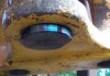
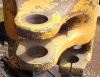
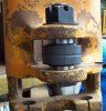
Those upper bushings are 1-1/4 in. wide. The lower bosses are 1-1/8 in thick so I'd be looking for the 1-1/8 in width, same 2 in. I.D.
If I have to go special sizes I was considering going to flanged drill bushings. Also the meat is a little thin in this area so was considering some weld build up to offset the bushing hole loss.
Also made my own boring bar from nitride coated shaft, 1-1/2 in dia. with broached holes for 1/2 in. tool bits. Drive will be my Milwaukee mag base drill through a couple of Sunnen 5/8 in. threaded universal joints.
Pretty amazing what you guys tackle for line boring.
")
Old Magnet can you post some pictures of it.
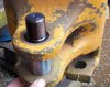
How about the pins with a flange like cat uses that takes a 1/2 13 bolt to lock the pin. what is the total length from outside to outside of the bottom earsYes, that's one of the options being considered.....or just welding a couple of key stock tabs up against the flats. The tower is cast steel so it would accept the welds. Or a tab welded to the pin flat and bolted to the tower similar to what you describe.
No, I don't see any need for the pivot bolt to rotate, in fact it's better if it doesn't.
Thanks for the suggestion.