oversize:
The article below explains the function of GPS on a machine. (In this case a grader). For the purpose of understanding the principle, you can equate GNSS with GPS.
__________________________________________________
Automating your World
with Neil Other
Earthmoving Equipment Review Magazine – August issue 2008
In this issue we will take a closer look at the parts that constitute a 3D machine control system. If you are in the construction industry, it is hard not to notice all the press about these systems and how they are helping to both reduce cost and to speed up construction. We’ll show you which parts actually go on your machine and how they work together to provide you accurate cut/fill information wherever the machine is on the job site.
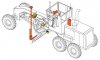
The diagram shows a motor grader with the main components of a 3D system and their approximate placement on the machine. Here we are using a single-antenna GNSS-based 3D system as an example which is what you will encounter most often on a job site. GNSS stands for Global Navigation Satellite System and includes the GPS, GLONASS and Galileo satellite systems. Variations on this 3D system and other positioning technologies are also available. We will be examining those in future issues.
Illustrated in yellow (and clockwise from the top) are the main fall slope sensor, the blade rotation sensor and the blade slope sensor. These are the basic components that along with an operator control box and a valve assembly make up a simple motor grader cross-slope system. The cross slope system has been around for a long time and allows the operator to dial in a desired cross slope that the system should maintain. Using the input from the above-mentioned sensors, the control box calculates which blade slope that will result in the desired cross slope for the particular blade rotation the operator is currently using. This information is then used to drive the lift cylinder on the side of the machine the operator has selected to be automated. The other lift cylinder is controlled manually, with a laser receiver or with a sonic sensor.
The cross slope system is an easy-to-use, low cost system that is very versatile. However; if the lift cylinder not controlled by the cross slope system is manually controlled, the elevation and quality of the final cut may not be as good as desired. Using a laser will get you an accurate height reference, but you are limited to working in planes. Stringline can be used instead of a laser and let you grade a vertical curve, but stringlines are costly to set and there is always the potential for errors in setting them.
Enter GNSS. If we can get an accurate 3D position in real-time on one corner of the blade, the cross slope system can maintain the other corner. On a mast bolted directly on the blade, we mount a rugged GNSS antenna. (The antenna is mounted on a mast because it needs to be higher than the cab of the machine in order for it to get a clear line of sight to the satellites). The signals received by this antenna travels to the GNSS receiver (in red, behind the cab in the illustration) which decodes and processes them and in turn sends them to the control box. The placement of the receiver is not important. It can be placed in the cab or in any other compartment. The operator does not need to access this on a regular basis. Usually it is magnetically mounted so it can be easily removed if needed.
The GNSS receiver also contains a radio receiver which receives correctional signals from a GNSS base station on or near the job site. In order for the machine control system to calculate an accurate position for the cutting edge of the blade, the receiver needs to get both the signals from the on-machine GNSS receiver and a correctional signal via a radio from what we refer to as a ‘base station’. This base station consists of a GNSS antenna and receiver along with a transmitting radio that broadcasts the correctional signals to the machine. The receiving radio antenna is mounted on top of the cab and can be seen in the illustration.
The brains of the operation is the control box. This component does a number of things: It receives the input from all the sensors and from the GNSS receiver, it holds the data model (the digital site plans), it serves as the operator interface and it provides the output to the hydraulic valves.
The control box is always placed inside the cab. It should be in the view of the operator and easily accessible. However; for safety reasons it is important that the mounting doesn’t obscure the operator’s view of the direction of travel. It should also allow a clear view of the blade so the operator can manage the material. The most common placements in motor graders are in close vicinity of the steering wheel. For joystick-controlled graders, it is most often placed in the lower part of the centre console.
In very simplistic terms; the control box uses all the inputs to calculate the exact 3D position of the cutting edge of the blade several times per second. The system then looks in the data model to see what the design elevation should be at this exact spot on the job site. The difference between where the cutting edge is and where is should be is your cut/fill information. This cut/fill information is displayed to the operator in real time on the screen of the control box. Additionally; if the operator has set the system to automatic mode, the cut/fill information will be sent to the valves so the blade can be automatically driven to the design elevation.
Installation of these component is another story altogether. It is important that your supplier of machine control systems is knowledgeable about not only the system they are selling you, but also about how you work with your machine and what kind of work you do. A good installer will consult with the machine owner and mechanic about component placement and routing of wires. It’s particularly important that the installer discusses the placement of the control box with the operator so that it is within reach and the screen can be read from the normal work position. Personal preference often plays a big part here.
I hope the above information will help you next time you speak to your dealer of machine control systems. Next time we will examine how the job site data gets from the paper plans and into the grade control system’s computer.
Grade well, grade quickly.
Neil

 ) in that it knows where the machine or more to the point, cutting edge is.