• Thank you for visiting HeavyEquipmentForums.com! Our objective is to provide industry professionals a place to gather to exchange questions, answers and ideas. We welcome you to register using the "Register" icon at the top of the page. We'd appreciate any help you can offer in spreading the word of our new site. The more members that join, the bigger resource for all to enjoy. Thank you!

Deere 350G LC Spool cap pressure spike

josiahnt

Member
Joined
May 19, 2021
Messages
10
Location
north Idaho
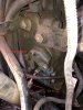
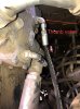
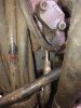
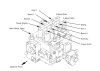
I have a 2012 350G 9000 hrs, that is building excessive pressure in a spool cap and actually cracking the mounting flange to relieve the excess pressure. This cap has been replaced with a brand new one and cracked again within 30 mins run time. My mechanic teed in a pressure gauge on it and routed it to the cab. The pressure seems to climb as soon as the oil starts warming up and in a few minutes will exceed 600 psi. Once the pressure starts to build, any operation of the machine causes it to climb, including traveling. I have included a couple pictures, one of the part on the machine and the part in the Deere diagram. Any ideas?

Screen Shot 2022-04-25 at 7.37.08 PM.jpeg IMG_6298.jpg
 

mg2361

Senior Member
Joined
Jul 5, 2016
Messages
5,126
Location
Pennsylvania
Occupation
Equipment Mechanic
Welcome to HEF josiahhnt;)!

First a serial number.

That looks like the cap for the auxiliary flow combiner valve. Make sure the hose in your picture has a clear path back to tank.

350G.png
 

uffex

Senior Member
Joined
Jan 23, 2012
Messages
4,464
Location
Lincoln UK
Occupation
Admin
Good day
May be of interest.
Kind regards
Uffex
 

Attachments

  • Fractured spoolCaps - FAR Servo pressure high.pdf
    461.5 KB · Views: 7

josiahnt

Member
Joined
May 19, 2021
Messages
10
Location
north Idaho
Thank you,
Serial # is 1FF350GXHCE808637
Full disclosure, I am the owner/operator, not a mechanic. I apologize in advance for my ignorance in terms and general knowledge of hydraulics. I've been searching the forums here for a while and learning a bunch. Threads for high pressure issues similar to this are much less common than low pressure issues.
I just acquired this machine last fall, I still have not been able to work with it because of this. I am learning more and more of the history as I go. I tracked down a service call from the previous owner to replace this cap, I will include it here, so it's been an issue for a while now. I believe they used this for the thumb valve when they installed it. I will check for failure and verify where it runs today.
Screen Shot 2022-04-26 at 7.13.51 AM.png
 

uffex

Senior Member
Joined
Jan 23, 2012
Messages
4,464
Location
Lincoln UK
Occupation
Admin
Good day
The post if I interpret correctly states that the spool cap failure and pressure increase is isolated to this one spool, it appears that this pilot line has connection to main pump pressure which exceeds the normal 5-600 psi the caps are designed for. I guess you do not have a hydraulic schematic for the machine. I can only suggest you follow the hose lines to see where it connects.
Kind regards
Uffex
 

josiahnt

Member
Joined
May 19, 2021
Messages
10
Location
north Idaho
Correct, I do not have a hydraulic schematic, yet. I have been looking at the Deere manuals and my guess is it would be found in the test procedures book?
So I followed the line, it tees at the cap with a short line going right back in to the valve bank and another going in to the top side of the thumb valve. I don’t have time to pull them and check for internal hose failures today, they both look great externally, I plan to do that tomorrow.
 

Attachments

  • IMG_7286.jpeg
    IMG_7286.jpeg
    3 MB · Views: 15
  • IMG_7285.jpeg
    IMG_7285.jpeg
    909.9 KB · Views: 13
  • IMG_7284.jpeg
    IMG_7284.jpeg
    2.8 MB · Views: 13
Last edited:

josiahnt

Member
Joined
May 19, 2021
Messages
10
Location
north Idaho
Good day
May be of interest.
Kind regards
Uffex
Fractured spoolCaps - FAR Servo pressure high.pdf

This is very interesting, it is the exact symptom I am experiencing.
When it references the pump relief valve filter, the drawing looks like that's the main pump, is there just one? From the Deere parts reference diagram it looks like there are relief valves inside the valve bank, could it be one of these?
 

Attachments

  • Fractured spoolCaps - FAR Servo pressure high.pdf
    461.5 KB · Views: 2

uffex

Senior Member
Joined
Jan 23, 2012
Messages
4,464
Location
Lincoln UK
Occupation
Admin
Good day
The attachment I posted affected most if not all the spool caps I guess this is not the case with your machine. I suggest you remove the line from the spool cap > plug the spool cap with a gauge checking where the high pressure is sourced > plug the open line and test. repeat the process on the remaining connections. If you have a port illustration of the main valve block in the manual please post it will help.
Kind regards
Uffex
 

josiahnt

Member
Joined
May 19, 2021
Messages
10
Location
north Idaho
Good day
The attachment I posted affected most if not all the spool caps I guess this is not the case with your machine. I suggest you remove the line from the spool cap > plug the spool cap with a gauge checking where the high pressure is sourced > plug the open line and test. repeat the process on the remaining connections. If you have a port illustration of the main valve block in the manual please post it will help.
Kind regards
Uffex

This got me wondering if the others on my machine may be affected?
Is it possible this is just the first one in the circuit building enough pressure to fail.
 

uffex

Senior Member
Joined
Jan 23, 2012
Messages
4,464
Location
Lincoln UK
Occupation
Admin
Good day
Manuals look a tad expensive, I suggest make an appeal on HEF for schematic often as not one of the guys will be able to post one to you.
Tool King is a great guy to help out in this respect. If you have a gauge check to see if the pressure is coming from the spool direction.
Kind regards
Uffex
 

mg2361

Senior Member
Joined
Jul 5, 2016
Messages
5,126
Location
Pennsylvania
Occupation
Equipment Mechanic
Based on your serial number you need TM12173 Operation and Test manual. TM12173 will get you machine diagnostics and schematics. It does not include engine diagnostics or the repair procedures (the one Uffex linked above).
 

uffex

Senior Member
Joined
Jan 23, 2012
Messages
4,464
Location
Lincoln UK
Occupation
Admin
Good day
Take a carefull check it may be the same as Hitachi see attched.
Kind regards
Uffex
 

Attachments

  • Hitachi 350.png
    Hitachi 350.png
    220.4 KB · Views: 8

josiahnt

Member
Joined
May 19, 2021
Messages
10
Location
north Idaho
The solenoid valve assembly mounted on the right side of the MCV. There is a port marked "DN". If there is a hose connected to it where does it go?

My lack of knowledge is really going to show here, I apologize in advance. I purchased the manuals, I am going to need to spend quite a bit of time poring over them to familiarize myself. I am trying to make sense of the hyd. schematic right now.
That being said, the port marked DN is in this pic.
IMG_7299.jpeg
If it is the one above the marking, (red arrow), this line goes back to a block in front of the pump, to a port marked T
IMG_7310.jpeg
If it is the one below the marking (green), this line goes to a block below the air filter here.
IMG_7308.jpeg
From this diagram, I believe the cap is for the Auxiliary function flow combiner valve. For what it's worth, the thumb on this machine was installed by a dealer that is not a Deere shop. I am starting to suspect the thumb install may have coincided with this issue starting with the previous owner. The previous owner traded machine in shortly after having the thumb installed.
I am getting a new cap, or this one brazed up and some gauges to test which side the pressure is coming from.
Screen Shot 2022-04-27 at 7.52.19 PM.png
 
Last edited:

uffex

Senior Member
Joined
Jan 23, 2012
Messages
4,464
Location
Lincoln UK
Occupation
Admin
Good day
In a normal installation the spool caps will have two connections (One each) both will connect to a remote control can be solenoids or remote control valve (RCV). A pilot line that has a "T" connection is a little strange. See attached may help.
Kind regards
Uffex
 

Attachments

  • JD 350D MCV Ports.pdf
    2.8 MB · Views: 7

mg2361

Senior Member
Joined
Jul 5, 2016
Messages
5,126
Location
Pennsylvania
Occupation
Equipment Mechanic
The aux flow combiner cap and the one port on the selector valve both need to go to tank. What is happening is the normal leakage within the spool itself leaks into the cap area. Since the cap has no path to tank the pressure eventually builds in the cap and then it breaks. The cap is supposed to be plumbed to the DN port of the solenoid valve and the selector valve port pictured below is supposed to be plumbed to the DM port of the solenoid valve. You can, if it is easier, just tee into one of the tank ports and run both to that.


Selector valve.png

DN Port.png
 

josiahnt

Member
Joined
May 19, 2021
Messages
10
Location
north Idaho
Does this short line teed off of the cap make any sense (red arrow)?
Assuming the T will go away and the line from the thumb valve to the DM port, do I leave this one?
IMG_7284.jpeg
Screen Shot 2022-04-27 at 7.52.19 PM.jpeg
 
Top