• Thank you for visiting HeavyEquipmentForums.com! Our objective is to provide industry professionals a place to gather to exchange questions, answers and ideas. We welcome you to register using the "Register" icon at the top of the page. We'd appreciate any help you can offer in spreading the word of our new site. The more members that join, the bigger resource for all to enjoy. Thank you!

Cat 325c How do i set up hydraulics for thumb?

bigcam

Active Member
Joined
Aug 17, 2018
Messages
33
Location
nebraska
Post #14 shows the starboard side hose running back to the tank and not having a three way valve, manual or electric. Apparently you can only run motor functions on the auxiliary side. Your machine does not have total tool control.

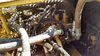
I don't know boat terms and had to google that lol But the hose on the right side of the arm is the side that gets pressurized when you hit the peddle on the floor. I couldn't really get a pic of it but it runs around behind all them valves and plums back into them on the backside. Nether hose goes back to the tank.
 

John C.

Senior Member
Joined
Jun 11, 2007
Messages
12,870
Location
Northwest
Occupation
Machinery & Equipment Appraiser
I don't recall any function hoses connecting behind the valve. If it is back there it likely connects to the hydraulic oil cooler. The starboard hose would be on the side of the hydraulic tank. All the units from the factory and all that were plumbed by the dealer in my area put the pressure hose for a breaker/compactor on the side of the cab. If you do have something different and the tank side hose does pressurize, then you only have a one way set up on your controls. It would likely just need someone to check out the software or you might have to add a two way control control valve. I don't think so though because you have the fancy handles with the proportional rockers. The wiring and valve are likely already in place.

You should call your Cat dealer and ask them some questions. Maybe they sold it and put it together.
 

John C.

Senior Member
Joined
Jun 11, 2007
Messages
12,870
Location
Northwest
Occupation
Machinery & Equipment Appraiser
I don't see on the line sheet where the extra plumbing and the two pump flow modification was added?
 

bigcam

Active Member
Joined
Aug 17, 2018
Messages
33
Location
nebraska
I don't recall any function hoses connecting behind the valve. If it is back there it likely connects to the hydraulic oil cooler. The starboard hose would be on the side of the hydraulic tank. All the units from the factory and all that were plumbed by the dealer in my area put the pressure hose for a breaker/compactor on the side of the cab. If you do have something different and the tank side hose does pressurize, then you only have a one way set up on your controls. It would likely just need someone to check out the software or you might have to add a two way control control valve. I don't think so though because you have the fancy handles with the proportional rockers. The wiring and valve are likely already in place.

You should call your Cat dealer and ask them some questions. Maybe they sold it and put it together.

Back in post #4 i explained what 2 cat dealers told me. My guess this machine came from another state based on the seller we bought it from said he got it out of state. I can also believe fairly easily things was not done normal since the manual thumb you see in the pic does not actually fit the machine and is rated for up to 45,000lb machine. I think one of the past owners probably pieced this and that together a bit and or went the cheap rout. So it seems as tho the idea of adding the right size hydraulic thumb is going to end up more then it is worth. For the kind of money needed for the valve plus the hydraulic thumb and have a cat dealer come out is probably pretty close to the cost of a grapple that don't use the AUX lines and only the bucket tilt cylinder to open and close.

I did gain another question tho. What are them valves in the pics on my posts #18 and #19? They look like they was added later?
 

John C.

Senior Member
Joined
Jun 11, 2007
Messages
12,870
Location
Northwest
Occupation
Machinery & Equipment Appraiser
You can trace the hoses on the valve mounted above the pump and I'm guessing they go to that auxiliary function. I would guess one of the ones mounted on the floor is for the two pump function and the other might be for two speed travel of something. As far as not worth the cost, everyone I know that resisted a hydraulic thumb would never have a machine without it after they got one. It will pay for itself in a hurry.
 

bigcam

Active Member
Joined
Aug 17, 2018
Messages
33
Location
nebraska
The peddle all the way to the right on the floor is for both tracks to run the same speed forward or back. The peddle to the left that is not mounted and only 1 way runs the AUX.

A grapple would work better for what we need to do. Wipe out trees and handle some scrap iron. We are not a construction company. Just need a bunch of stuff cleaned up at the farm. We borrowed a excavator earlier this year with a hydraulic thumb and it really was only helpful to get the thumb up to push the dirt back into the root hole of a tree. Witch we could still do with a grapple. At lest the type we are looking at. Just figured a hydraulic thumb might be the cheaper way to go. But at the cost of 6k for a hydraulic thumb plus buying valves, having cat come out and figure out this mess and having to cut off that undersized thing that is on there VS about 10k for a new grapple and knock a few pins around and we are moving trees. Less down time and a better working tool for about the same cost as i see it. We do have the quick attach for this machine so we can swap back to the bucket for digging pretty easy. The last owner pulled the quick attach off thinking that short thumb might actually work then. Nope it is still to short.
 

bigcam

Active Member
Joined
Aug 17, 2018
Messages
33
Location
nebraska
This is how it was originally shipped when new in 2005.

You seem to be able to find all the details. Are you able to get any more details on this valve from its part number?
 

Attachments

  • IMG_20180818_150655609_HDR.jpg
    IMG_20180818_150655609_HDR.jpg
    2.7 MB · Views: 15

bigcam

Active Member
Joined
Aug 17, 2018
Messages
33
Location
nebraska
That valve was only ever used on the 315. It looks like someone has been "bush engineering" prior to you buying the machine.
See attached.
Yea it looks like a few things was done with "bush engineering" on this machine lol But knowing what was done may become very important in the future if we ever need to do a repair on something. I am also very interested to know how that valve works and why the lower port on it has a block off plate. Being very ignorant about these valve systems but know enough about other hydraulics i wonder if that blocked off port would be for running a 2 way cylinder. If not still a good thing to know what it does or don't do since it is not something normally on this machine. The rest of the machine i am sure is in the repair manual but a odd ball valve never meant for this machine surly wont be in the repair manual.
 

Nige

Senior Member
Joined
Jun 22, 2011
Messages
29,364
Location
G..G..G..Granville.........!! Fetch your cloth.
Sorry I never really looked too close at the photos. I wonder if in an attempt to add an extra function someone has replaced one half of the original main control valve from the machine with the 171-0140..? 171-0140 contains seven spools, each half of the "correct" valve for your machine has five.
 

Attachments

  • 258-0281.pdf
    174.6 KB · Views: 4

John C.

Senior Member
Joined
Jun 11, 2007
Messages
12,870
Location
Northwest
Occupation
Machinery & Equipment Appraiser
I'm thinking that is the tag seen on the auxiliary valve. If so I think it fits most of the mid size machines. The hose coming out of that valve is going down the cab side of the boom indicating it is the supply to what ever function they were trying to run. The cap just below that hose would be the other side of that circuit if it was set up for two way function. The hose on the tank side disappears behind the main control valve and I'm sure is going to the hydraulic oil cooler. I don't know why it would stiffen when you energize the valve. There are other hoses in those photos of the valve I don't recognize so I don't know just what all was going on with the machine. In any case you have enough stuff on there to give you plenty of options for attachments should you wish to spend the money to install them.
 

bigcam

Active Member
Joined
Aug 17, 2018
Messages
33
Location
nebraska
Sorry I never really looked too close at the photos. I wonder if in an attempt to add an extra function someone has replaced one half of the original main control valve from the machine with the 171-0140..? 171-0140 contains seven spools, each half of the "correct" valve for your machine has five.

In this photo the far right valve is the one with the tag on it. Where the return seems to actually be coming into.
 

Attachments

  • IMG_20180818_150735983_HDR.jpg
    IMG_20180818_150735983_HDR.jpg
    2.8 MB · Views: 13

bigcam

Active Member
Joined
Aug 17, 2018
Messages
33
Location
nebraska
I'm thinking that is the tag seen on the auxiliary valve. If so I think it fits most of the mid size machines. The hose coming out of that valve is going down the cab side of the boom indicating it is the supply to what ever function they were trying to run. The cap just below that hose would be the other side of that circuit if it was set up for two way function. The hose on the tank side disappears behind the main control valve and I'm sure is going to the hydraulic oil cooler. I don't know why it would stiffen when you energize the valve. There are other hoses in those photos of the valve I don't recognize so I don't know just what all was going on with the machine. In any case you have enough stuff on there to give you plenty of options for attachments should you wish to spend the money to install them.

It not only stiffens but really pulls down the engine. I wouldn't think a oil cooler could handle such pressure and it has a 90* elbow back there going into the back of a valve. I will try to make a better attempt next time i am out by the machine to get a pic and show which valve it is hooked to. Things really get tight on the backside of them valves lol
 

Cmark

Senior Member
Joined
Jan 2, 2009
Messages
3,178
Location
Australia
If I can stick my oar in a little.

I believe the part number on the tag is 1710146 which is for an auxiliary valve which does fit this machine, but has been added later. The main control valve is essentially two separate valves, left and right, which each receive flow from one pump. The standard auxiliary valve is on the left section, fourth from the left (looking towards the engine). Now if we look at post #17, photo 2 we can see a line from the standard auxiliary valve crossing over and combining with the line from the added valve on the end ot the right section. I therefore deduce, Watson, that someone has added the 1710146 valve and crossover line to get one-way two-pump flow, probably for a hammer.

It should be fairly easy to get two-way one-pump flow by removing the crossover line and plumbing directly into the standard auxiliary valve. Retaining the option of having two-pump flow would be more tricky, but that wouldn't be needed for a thumb.
 

bigcam

Active Member
Joined
Aug 17, 2018
Messages
33
Location
nebraska
If I can stick my oar in a little.

I believe the part number on the tag is 1710146 which is for an auxiliary valve which does fit this machine, but has been added later. The main control valve is essentially two separate valves, left and right, which each receive flow from one pump. The standard auxiliary valve is on the left section, fourth from the left (looking towards the engine). Now if we look at post #17, photo 2 we can see a line from the standard auxiliary valve crossing over and combining with the line from the added valve on the end ot the right section. I therefore deduce, Watson, that someone has added the 1710146 valve and crossover line to get one-way two-pump flow, probably for a hammer.

It should be fairly easy to get two-way one-pump flow by removing the crossover line and plumbing directly into the standard auxiliary valve. Retaining the option of having two-pump flow would be more tricky, but that wouldn't be needed for a thumb.

Well i hope you are right! If you are what switch's direction of flow tho i wonder? And being John C keeps stating normally the line on the cab side is the pressure side that would make sense for the 2 pump worth of flow since that side has 2 lines running into 1. Some reason this machine is pressurizing the side not next to the cab. This leaving me thinking maybe they have it plumbed as John C stated and some how i am getting reverse flow from what he stated thus making me think there might very well be a way to run both ways only the 1 way i would have 2 pumps worth of flow and the other way 1 pump worth of flow.

I think i need to find for sure what valve that line runs into on the back side and maybe play with switches in this machine. Maybe one of them possibly marked wrong and actually switches flow direction??? Worth trying i think. If not then see how as you said Cmark that line should be plumbed into just the 1 valve 4th from the left. Or is that cross over line already plumbed into the correct place on that 4th valve from the left?
 

Cmark

Senior Member
Joined
Jan 2, 2009
Messages
3,178
Location
Australia
If the line away from the cab is getting pressure, then yes, find out where on the MCV it goes to. You may be right, it could have two way flow and maybe just needs turning on. Have you checked the tool control options in the monitor?

If you were starting from scratch and fitting two way aux for a thumb, you would simply run the two lines into the two ports on the fourth valve.

Is the crossover line correct? I would say it looks like a pretty kosher installation, probably done by a Cat dealer, so you would have to assume it is correct for what it was designed for.
 
Top