• Thank you for visiting HeavyEquipmentForums.com! Our objective is to provide industry professionals a place to gather to exchange questions, answers and ideas. We welcome you to register using the "Register" icon at the top of the page. We'd appreciate any help you can offer in spreading the word of our new site. The more members that join, the bigger resource for all to enjoy. Thank you!

CAT 299D won't move

Nige

Senior Member
Joined
Jun 22, 2011
Messages
29,315
Location
G..G..G..Granville.........!! Fetch your cloth.
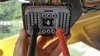
They are, but I strongly suggest that you double-check using the wire numbers and colours just to make sure. All wires have a number marked on the insulation all the way down their length.

The J1 & J2 connector Pin numbers are marked on the outside of the plug where the Allen screw is. The way the numbers refer to pins is not totally intuitive, make sure that you understand the numbering system before placing 100% reliance on your ability to determine which pin is which. After many years I still have to think about it.....
 
Last edited:

Jeffrey Bandel

Senior Member
Joined
Jul 25, 2019
Messages
345
Location
Radford, Virginia
With a flashlight and magnifying glass I was able to read them. Resistance was close to 0 ohms. I tried test 3 but got nothing. When I got home I read the instructions again. It doesn't say to hook the battery back up but I assume you do?
 

Nige

Senior Member
Joined
Jun 22, 2011
Messages
29,315
Location
G..G..G..Granville.........!! Fetch your cloth.
OK, here's what you need to do. Key stays off, the speed sensor stays disconnected from the machine harness, and Connector J2 remains disconnected. You do not need battery power, this is a resistance test looking for a possibility that 2 wires (one of which will be one of the two speed sensor signal wires) are shorted together somewhere inside the machine wiring harness.

Set the DMM to measure resistance and put one probe in Pin #29 (Wire #834 yellow) of Connector J2. Then put the other probe of the DMM in turn into every other terminal in Connectors J1 and J2 that has a wire in it and obverve the resistance. There are 33 wires in J2 and over 60 in J1. In every case the resistance must be 5000 ohms minimum. When you have done that, move the first probe from Pin #29 to Pin #37 (Wire #835 Purple) of Connector J2 and repeat the test as before.
 
Last edited:

Nige

Senior Member
Joined
Jun 22, 2011
Messages
29,315
Location
G..G..G..Granville.........!! Fetch your cloth.
If the DMM is set to resistance and the reading is over 5000 ohms it usually dispalys a message something like "OL" (open circuit effectively). When you say you got "no reading" does that mean that the meter read "OL" every time you tried to measure resistance between 2 diiferent wires..?

To be thorough you have to start with one speed sensor signal wire and measure the resistance between it and every other wire in turn in both J1 & J2. Then when you have done that you go back and start at the other signal wire and do the exact same again. It may seem a pain but it's the only way of making sure you don't have an obscure short circuit inside a harness somewhere.
 
Last edited:

heymccall

Senior Member
Joined
Feb 19, 2007
Messages
5,376
Location
Western Pennsylvania
Dumb question, having just briefly peruse the troubleshooting tree, have the signal wires on the sensor itself been tested.
Being a hall effect sensor (I assume) like the wheel speed sensors on my trucks, I test them looking for 1k ohm across the signal wires. With these having four wires (my trucks have 2), is that part of the sensor even testable?
 

Nige

Senior Member
Joined
Jun 22, 2011
Messages
29,315
Location
G..G..G..Granville.........!! Fetch your cloth.
They are PWM sensors rather than Hall Effect. The only check is to remove them and check the sensor end is clean. That's the next (and last) step in the diagnostic process. The last step is to see if the Diagnostic Code has disappeared.
As far as I can see the Troubleshooting procedure revolves around testing the sensor power & return wires, testing continuity of the signal wires to/from the ECM, testing for an internally-shorted harness, and if all that shows nothing and the business end of the sensor is clean the implication is that the sensor is bad.
 

Jeffrey Bandel

Senior Member
Joined
Jul 25, 2019
Messages
345
Location
Radford, Virginia
This is what I'm doing. The meter is always on open loop. 0.L.
If I touch the leads together I get 0.00
 

Attachments

  • 0807191111_HDR.jpg
    0807191111_HDR.jpg
    4.7 MB · Views: 21
  • 0807191111.jpg
    0807191111.jpg
    5.9 MB · Views: 18

Nige

Senior Member
Joined
Jun 22, 2011
Messages
29,315
Location
G..G..G..Granville.........!! Fetch your cloth.
You are definitely doing the test correctly, and the fact that every one you tried so far came up OL is good. However back to your previous post when you said that you only tested “about 8”. You need to test every wire in both J1 & J2 to one speed sensor signal wire (so about 90 wires give or take between the two connectors), then go back and Move one DMM probe to the other speed sensor signal wire and do exactly the same again. Only by testing every other wire in the harness to each signal wire in turn can you be sure that there is not an internal harness short circuit somewhere. The one you miss could be the one that is shorted.
 

skata

Senior Member
Joined
May 10, 2007
Messages
1,541
Location
midwest
Wouldn't there be more likely a break in the wire if there was a wiring issue? In that case, you can't really test, unless you know there is suppose to be a certain resistance.
 

Nige

Senior Member
Joined
Jun 22, 2011
Messages
29,315
Location
G..G..G..Granville.........!! Fetch your cloth.
If you go back to the troubleshooting procedures I posted a couple of pages back, the test for continuity of the two signal wires was done by putting a jumper between the two at the sensor end and measuring the resistance of the loop from the ECM end. That tested our OK.
The problem with PWM sensor signals is that they can track across wires within a harness if there is an insulation fault buried somewhere in the harness. That’s the purpose of the test for an internal harness short.
To the OP. Sorry it’s going to be more work but disconnect the RH sensor and do the same test for an internal short on the two signal wires for that side of the machine while you are in there. Might as well tick that box at the same time.
 

Nige

Senior Member
Joined
Jun 22, 2011
Messages
29,315
Location
G..G..G..Granville.........!! Fetch your cloth.
Sorry, my mistake. I thought the dodgy wiring you found was on the left side.
The chance of an internal harness short is low, but if you don't test for the possibility and crash on regardless "assuming" the harness is good it has the potential to cause all sorts of problems.
 

Jeffrey Bandel

Senior Member
Joined
Jul 25, 2019
Messages
345
Location
Radford, Virginia
I have completed all of test 3. It all checks out. It moved about 20 feet forward and then I tried to turn left and it locked up again. Turned it off and same thing. It seems every time I use the left joystick it locks up. I know I read somewhere in the repair manual about a correlation between the left joystick and locking the parking brake...

ps. I know I still need to check the actual motor speed sensors but the left joystick is taking priority.
 
Top