Hello Darren, Sorry I had not checked my emails, it has been a very bad week for me.
No I didn't get any info on the forum, however I found an old friend of mine that had retired from Case power. He put me in contact with an other guy here in San Antonio that had quote "cut his teeth on these old machines". Most of the old guys are retired or have passed on. So I went by there and he let me look at an old service manual and explained how it come apart.
So you have to split the tractor all the way back to where the transmission starts. The engine has to come out of coarse, mine was out already out for rebuild, the console had to be lifted up by the ROPS cab with straps and come-a-long, all the steering, hydraulic lines, fuel tank, battery, battery box, brake linkages, brake pedal assy, top shuttle plates and torque converter charge valve ect. has to come off. Don't get discouraged when pulling the top plates. The large one has two dowels in it, and it is hard to get off!!! The dowels keep the charge pump aligned. Then you split the cases at the back of the shuttle. Be very careful not loose the shims and snap ring at the rear, where the shuttle splines to the transmission. When reinstalling the shuttle case assy. I think there has to be a minimum gap of .025 and a maximum of .045 at those shims IIRC.
Once the shuttle is out, the friction pack will slip out the back of the case, after removing one bolt and retaining washer, and gear. There is a spanner nut on the back of the assembly. remove that and the planet gear. There are some thrust bearings and washers in this area, keep them organized. That is the easy part. Then you need to have a press of good size, put the long end downward in the press, this end has the snap ring recessed in the last plate. Push the shaft down through the assembly. There is a long square key that goes all the way through keeping everything aligned. Now once you are pressing and it take some pressure because you will be moving the entire stack off the shaft at one time! Press until the first plate becomes loose. stop and unstack the frictions, keeping them in order and pay close attention to the inner bellville flat springs between them and the plates. There are timing marks on the spline, on the shaft that spline into the slick plates, they are 5 teeth apart and each bellville spring has to be in the correct place. When you are stacking the plates the first bellville spring will line up on the right mark then the second will line up on the left mark and so on alternating. All this does is align the waves of the spring. Also at this time there are some very thin small shims in the center of the stack. These set up the distance the piston has to travel to engage the clutch pack. Keep them in order too! Once that is unstacked then continue pressing until the center piston assy. comes loose. Now there are two lubricating valves and springs in the piston, pay attention how they are positioned. Now that the piston assy. is off then you can unstack the second set of frictions, plates, shims ect. Once all the loose parts are off the shaft, you can turn over the shaft and press the first plate right back down into position, back against the snap ring and you are ready to clean it up and start the reassembly. If you have any book on this you will see a set of U-shaped steel tool plates that hold the friction set together. All these do is hold the frictions and springs together while you press the piston back on. These tools are not sold by Case any more, so you either make them or borrow them.
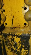
On the long torque tube shaft there are three locking piston rings. Check the torque tube case where these rings ride down inside, if there is ware there you might have to take the tube/case to a machine shop and have it bored out and put a sleeve back in to bring it back into tolerance? The rest of the shuttle case is pretty straight forward, just gears and bearings.
The torque converter is pretty simple too. If you have ever done a converter on any Caterpillar it is about the same. The rebuild kit for the converter is basic.
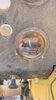
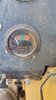
Make sure and check your pump for ware too. I had pressure problems with my hoe and did the drill out and tap the bottom of the case to clean the suction screen, well the screen was damaged and I had epoxied it back in place through the tapped hole. After pulling the top plate and looking at the pump and suction tube, I feel that the screen was never adequate in the first place. I am going to redo my screen and increase the area of it.
The Twin Disc shuttle is more work but I think it is a good one. I hope you are as lucky as I was. My frictions look like new and all I needed was seals and gaskets. I did this because there was a lot of debris in the system and was worried that the apply pistons were full of junk and would fail after putting the new engine back in. However the pistons were clean, just were in need of new seals. The old ones were deteriorating going bad. The frictions plates alone are real costly. I spent over $800.00 just for seals and gaskets.
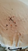
My engine, shuttle, and transmission had so much crap in them, that I feel it must have been in the flood of 1998, here in central Texas.
Well Darren, I hope this helps you. If you need anything else let me know. I will help if can.