• Thank you for visiting HeavyEquipmentForums.com! Our objective is to provide industry professionals a place to gather to exchange questions, answers and ideas. We welcome you to register using the "Register" icon at the top of the page. We'd appreciate any help you can offer in spreading the word of our new site. The more members that join, the bigger resource for all to enjoy. Thank you!

Advice on adding a Pullmaster winch to WA250-1

Monkeywithawrench

Senior Member
Joined
Nov 8, 2019
Messages
313
Location
New Hampshire
I need to add a winch to a Komatsu WA250-1. I'll be putting a Pull Master H10 onto the machine. My question is....is there a power beyond port anywhere on this machine?? The machine has the stock 2 spool valve setup for bucket lift and dump. I thought about tagging into the return line off the valve block but its a solid steel line off the block to a manifold block by the tank. That means taking the line off, cutting, welding, and then plumbing the motor spool valve in.
Looking at the service manual and at the machine, I don't see any extraneous ports that I might be able to unplug and tap into on the hydraulic pumps.
Has anybody added a grapple or 3rd function to one of these and, if so; how did/would you go about plumbing into this??

Thank you!!!
 

Tones

Senior Member
Joined
Mar 15, 2009
Messages
3,078
Location
Ubique
Occupation
Ex land clearing contractor, part-time retired
You could plumb in one of the existing circuits after the control bank, fit a electric change over valve. That way you'd then use the lever to operate the winch
 

Monkeywithawrench

Senior Member
Joined
Nov 8, 2019
Messages
313
Location
New Hampshire
So that would be the steel return line running from the valve block to a junction block just 'afore the hydraulic tank. Trying to avoid taking the line off/out, cutting the end off, shortening it, and then rewelding it.
Seems like there should be a simpler, easier way. Was............and still am, hoping someone with a more intimate knowledge of this machine might tell me of an easier simpler way to my pot o'gold.
But Thank You Tones!! Appreciate the idea!!
 

John C.

Senior Member
Joined
Jun 11, 2007
Messages
12,870
Location
Northwest
Occupation
Machinery & Equipment Appraiser
Are you buying the winch used or new. The manufacturer many times has kits for installing in many different machines. In general on loaders you need a three section valve to run things like clamps or quick couplers. The diverter valve on the boom or bucket tilt circuit as Mr. Tones suggests is probably the easiest way to plumb it in. I don't know that I've ever seen a Komatsu wheel loader with a power beyond port.
 

Monkeywithawrench

Senior Member
Joined
Nov 8, 2019
Messages
313
Location
New Hampshire
I'm doing this for a boat yard. The winch is used.......its sitting in the back of the service truck as we speak. I guess they had it on another previous loader. And I haven't spoken with Pull Master yet.......good point, I'll call them on Monday. I thought about adding a 3rd valve to the valve pack but you need a motor spool valve setup for the winch to work.
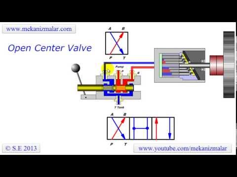
I'll explain the operation of the winch just in case someone else reads this and is unfamiliar. When pressure is applied to the motor to run the winch in forward or reverse, it also applies hydraulic pressure to the spring brake through a line coming off the motor. The pressure from the motor to the spring brake releases the spring brakes which releases the drum. The valves used to control the lift cylinders or dump cylinder close off in the neutral position. The lines going to the winch need to be able to release all pressure in the neutral position so that the spring brake engages. A motor spool valve does this by dumping both lines to the motor into the return line.......and the system runs on an open center system.
So diverter valves on the lift or dump circuits wouldn't work. The float position might work to release all the pressure and let the brake come on.
 

Monkeywithawrench

Senior Member
Joined
Nov 8, 2019
Messages
313
Location
New Hampshire
upload_2021-5-8_12-26-6.png


hqdefault.jpg


upload_2021-5-8_12-6-2.pngupload_2021-5-8_12-6-2.png upload_2021-5-8_12-6-2.png
 

Attachments

  • upload_2021-5-8_12-25-24.png
    upload_2021-5-8_12-25-24.png
    74.5 KB · Views: 1

Nige

Senior Member
Joined
Jun 22, 2011
Messages
29,310
Location
G..G..G..Granville.........!! Fetch your cloth.
Just a thought. The diagram above has flow requirements for the winch motor but I don't see anything on the drawing regarding the maximum inlet pressure to it. It would be somewhat embarrasing to damage the motor by applying a pressure that was too high. I have no idea what the implement pump main relief valve is set at on the WA250, maybe John C might have an idea.

Also what struck me were the flow requirements, which are quite low compared to what I imagine the implement pump will supply. Going back to the comments above about a 3rd function valve (to control the winch in this case) any flow-reducing requirements would be addressed in that 3rd function circuit. Personally I've seen any number of attachments (but never a winch) that required a flow regulation valve in the 3rd function circuit before the control valve to supply a fixed GPM to the attachment and dump the rest of the flow straight back to tank.
 

Dave Neubert

Senior Member
Joined
Jul 18, 2018
Messages
1,660
Location
Monroe NC
I don't think you can plumb into the return line that would pressurize the control valve in places its not designed to be pressurized you need a 3rd valve many can be added on but some you have to change out the whole valve bank
 

Monkeywithawrench

Senior Member
Joined
Nov 8, 2019
Messages
313
Location
New Hampshire
Thank you all for your input!! This is exactly what I'm looking for......ideas and info.

I wish I had the intelligence, knowledge, and experience to just whip this together knowing how exactly to get it done.

So the winch has a max pressure of 2200 psi. The WA 250-1 hydraulic system runs at 3000 psi according to the manual. I forget what the flow is....I think its around 30-40 gpm with both pumps. There is a priority valve between the 2 pumps. I thought of plumbing into the power steering system. That has a lower gpm pump on it. I think that is 15-20 gpm. As for the 3rd valve option.......I don't know if you can just get the 3rd valve and bolt it in (I ASSume that would be the case) but I don't know. That still leaves the problem of having the lines dumping pressure so the brake can engage by dumping pressure from the winch motor when you stop running it.
 

Monkeywithawrench

Senior Member
Joined
Nov 8, 2019
Messages
313
Location
New Hampshire
so minimum flow is 11gpm and max flow is 37gpm for the winch, at 2200 psi.
So frustrating.........I've got 3 hydraulic pumps on this machine. You'd think there would be at least one pump with a plugged pressure port I could tap into. Add a pressure relief valve, flow regulator, a valve, some hose and PRESTO!! ..........one working winch!!
I do have a few flow/pressure gauges that I own for diagnosing motors, pumps, etc.
Unfortunately, the machine is an 1 hour 20 minutes away........one way. Maybe I just need to go spend some quality time with it and study the pumps, take some sheet metal off so I can get a better look at them.
 

Monkeywithawrench

Senior Member
Joined
Nov 8, 2019
Messages
313
Location
New Hampshire
So the valve assembly with 3 valves is part number 709-83-11102. Thats $10k when doing a quick search. When looking at the parts break down for the 3 valve setup, the middle valve block doesn't have a part number. I'll see if I can figure out how to get the parts break down loaded up onto this board. Haven't got that figured out yet either.
 

lantraxco

Senior Member
Joined
Jan 1, 2009
Messages
7,704
Location
Elsewhen
You need a valve, or valve section, with a motor spool, motor spools leave both work ports open to tank when in neutral. If when using the winch, no steering or slow steering is acceptable, then a three way solenoid valve diverting to a four way motor spool solenoid valve with a rocker or toggle switch to control the winch would work, as an example. To get some steering, put a flow divider inline with the diverted output, send some oil back to the steering gear through a tee with a check valve.
 

Monkeywithawrench

Senior Member
Joined
Nov 8, 2019
Messages
313
Location
New Hampshire
Thanks Lantaxco...........getting closer. Was thinking last night while falling asleep, that if I use a solenoid valve that it would have to be a modulating motor spool solenoid valve so you could have some speed control. A regular solenoid valve would just be (Bang) On/ (Bang) Off without any speed control.
Thogs brain bone hurt from thinking........:rolleyes:

Now!! Over the river and through the woods to Grammies house we go!!
Happy mothers day to all of you Motha's like me out there!! LOL
And thank you again for all your input.
 

4x4ford

Well-Known Member
Joined
Jul 20, 2007
Messages
239
Location
Las Vegas Nevada
Occupation
aunts on the strip Currently drive a 1951 chevy pa
What about a diverter going to a separate valve bank specifically for the winch with its own return and pressure relief plumbed to the tank then if it needs moved to another loader in the future would make it much simpler
 

Monkeywithawrench

Senior Member
Joined
Nov 8, 2019
Messages
313
Location
New Hampshire
Ok, lets see if this works.....trying to upload PDF's of the 2 spool control valve setup thats on the machine now, with part numbers, the optional 3 spool control valve that I wish the machine had, with part numbers. And the hydraulic circuit for the machine.
So it looks to me like the 3 spool control valve would be GREAT, but it doesn't look like the middle valve is available seperately because there are no part numbers with it. I don't see why the middle valve wouldn't be available. The 3 spool valve complete is $10k doing a quick search. If this works, then I'll upload the steering diagram next.
 

Attachments

  • WA250 HYDRAULIC CIRCUIT.PDF
    243.2 KB · Views: 3
  • 2-SPOOL CONTROL VALVE DIAGRAM.pdf
    53.5 KB · Views: 1
  • 3-SPOOL CONTROL VALVE DIAGRAM.pdf
    71.9 KB · Views: 3

Monkeywithawrench

Senior Member
Joined
Nov 8, 2019
Messages
313
Location
New Hampshire
Parts diagram and breakdown of hydraulic pump and steering pump with specs for WA250-1 loader
 

Attachments

  • wa250 HYDRAULIC AND STEERING PUMP.pdf
    72.1 KB · Views: 2
Top